Sign In
Upload
Download
Table of Contents
Contents
Add to my manuals
Delete from my manuals
Share
URL of this page:
HTML Link:
Bookmark this page
Add
Manual will be automatically added to "My Manuals"
Print this page
×
Bookmark added
×
Added to my manuals
Manuals
Brands
Advantech Manuals
Network Router
Libratum ICR-2834
Hardware manual
Advantech ICR-2834 Hardware Manual
Industrial cellular router
Hide thumbs
Also See for ICR-2834
:
Start manual
(9 pages)
,
User manual
(46 pages)
1
2
3
Table Of Contents
4
5
6
7
8
9
10
11
12
13
14
15
16
17
18
19
20
21
22
23
24
25
26
27
28
29
30
31
32
33
34
35
36
37
38
39
40
41
42
43
44
45
46
47
page
of
47
Go
/
47
Contents
Table of Contents
Bookmarks
Table of Contents
Table of Contents
Product Overview
Product Introduction
Product Usage Examples
Access to the Internet from LAN
Backed up Access to the Internet
Using VPN Tunnel
Serial Gateway
Hardware Overview
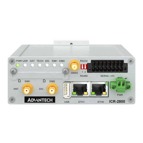
Hardware Overview of the Router
Hardware Overview of the Router
Order Codes
Order Codes Overview
Package Contents and Accessories
Product Dimensions
Mounting Recommendations
DIN Rail Mounting
Product Label
Hardware Functionality
SIM Card Slots
Antennas
Ethernet Interfaces
Ethernet Connector Pinout
Ethernet Connector Pinout Description
Power Supply
Low Power Mode
I/O Port Interfaces
I/O Ports Pinout
Serial Interfaces
Both Interfaces in RS232 Mode
Connection of the First Serial Interface Switched to RS232 Mode
Connection of the Second Serial Interface Switched to R232 Mode
Both Interfaces in RS485 Mode
Connection of the First Serial Interface Switched to RS485 Mode
Connection of the Second Serial Interface Switched to RS485 Mode
USB Port
USB Connector Pinout
LED Status Indication
Reset Functions
First Use
Accessories Connection
Router Configuration
Technical Specifications
Basic Parameters
Standards and Regulations
Type Tests and Environmental Conditions
Parameters of Cellular Module
Technical Parameters of Cellular Module
Parameters of Wifi
Technical Parameters of Wifi
Parameters of GNSS
Technical Parameters of GNSS
Parameters of I/O Ports
Parameters of Serial Interfaces
Electrical Characteristics of Binary Input
System Configuration
Appendix A: Troubleshooting
Advertisement
Quick Links
Download this manual
Hardware Manual
Industrial Cellular Router
ICR-2834
Advantech Czech s.r.o., Sokolska 71, 562 04 Usti nad Orlici, Czech Republic
Document No. MAN-0067-EN, revision from 20th October, 2023.
Table of
Contents
Previous
Page
Next
Page
1
2
3
4
5
Advertisement
Table of Contents
Need help?
Do you have a question about the ICR-2834 and is the answer not in the manual?
Ask a question
Questions and answers
Related Manuals for Advantech ICR-2834
Network Router Advantech ICR-2834 User Manual
Lte industrial router (46 pages)
Network Router Advantech Libratum ICR-2834 Start Manual
(9 pages)
Network Router Advantech ICR-2800 Hardware Manual
Industrial cellular router (47 pages)
Network Router Advantech ICR-2431 User Manual
Lte industrial router (44 pages)
Network Router Advantech ICR-2431 Hardware Manual
Industrial cellular router (44 pages)
Network Router Advantech ICR-2531 User Manual
Lte industrial router (41 pages)
Network Router Advantech ICR-2531 Hardware Manual
Industrial cellular router (41 pages)
Network Router Advantech ICR-2437 Hardware Manual
Industrial cellular router (44 pages)
Network Router Advantech ICR-2701 User Manual
Lan industrial router (35 pages)
Network Router Advantech ICR-2701 User Manual
Lan industrial router (34 pages)
Network Router Advantech ICR-2734 Hardware Manual
Industrial cellular router (42 pages)
Network Router Advantech ICR-2412 Hardware Manual
Industrial cellular router (44 pages)
Network Router Advantech ICR-2441 User Manual
Lte industrial router (41 pages)
Network Router Advantech ICR-2041 User Manual
Lte industrial router (40 pages)
Network Router Advantech ICR-2441 User Manual
Lte industrial router (41 pages)
Network Router Advantech ICR-2441 User Manual
Lte industrial router (43 pages)
This manual is also suitable for:
Icr-2800
Table of Contents
Print
Rename the bookmark
Delete bookmark?
Delete from my manuals?
Login
Sign In
OR
Sign in with Facebook
Sign in with Google
Upload manual
Upload from disk
Upload from URL


Need help?
Do you have a question about the ICR-2834 and is the answer not in the manual?
Questions and answers