Table of Contents
Advertisement
Quick Links
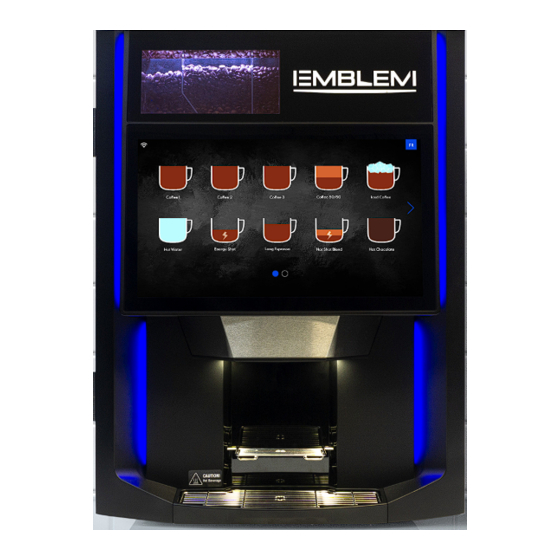
Images may vary from the actual product.
Table of Contents
1 SAFETY INSTRUCTIONS ..........................................................................................................................................2
1.1
Food-Contact Parts .......................................................................................................................................2
1.2
Warnings ........................................................................................................................................................2
1.3
Power Supply ................................................................................................................................................2
1.4
Disconnect the Equipment if: .........................................................................................................................2
2 BREWER SPECIFICATIONS .....................................................................................................................................3
2.1
External View .................................................................................................................................................3
2.2
Rear View ......................................................................................................................................................3
2.3
Internal View ..................................................................................................................................................4
2.4
Dimensions and Clearances ...........................................................................................................................5
2.5
Technical Specifications .................................................................................................................................5
3 INITIAL SETUP ..........................................................................................................................................................6
3.1
On-Site Installation Requirements ...................................................................................................................6
3.2
Chute Hole Cutting (Optional) .........................................................................................................................6
3.3
Unpacking .....................................................................................................................................................7
3.4
Leveling the Equipment ..................................................................................................................................7
3.5
Drip Tray Installation .......................................................................................................................................8
3.6
Side Skirts Installation ....................................................................................................................................8
3.7
Water Line Connection ...................................................................................................................................8
3.8
Electrical Connection .....................................................................................................................................9
3.9
Loading Products .........................................................................................................................................10
3.10 Filter Paper Installation .................................................................................................................................11
3.11 Chute Hole Hiding Plate Installation ..............................................................................................................11
3.12 Chute Kit Installation (Optional) .....................................................................................................................12
3.13 Installation Verification ..................................................................................................................................12
Manufactured by:
Evoca North America Venture Inc.
Tel.: 800-561-6162
service.na@evocagroup.com
QUICK
INSTALLATION
GUIDE
Fax: 800-463-2739
www.evocagroupna.com
Installation &
Service Manual
Available by scanning this
QR code.
23DOC12A - Revision 0 / 2023-10
Advertisement
Table of Contents

Summary of Contents for Evoca Group Cafection EMBLEM
-
Page 1: Table Of Contents
QUICK INSTALLATION GUIDE Installation & Service Manual Available by scanning this QR code. Images may vary from the actual product. Table of Contents 1 SAFETY INSTRUCTIONS ............................2 Food-Contact Parts ............................2 Warnings ................................2 Power Supply ..............................2 Disconnect the Equipment if: .........................2 2 BREWER SPECIFICATIONS .............................3 External View ..............................3 Rear View ..............................3... -
Page 2: Safety Instructions
QUICK INSTALLATION GUIDE LEGEND This symbol is used to highlight a key step to anticipate a risk for safety or a risk of damaging the equipment. This symbol is used to indicate additional information or a quick tip. 1 SAFETY INSTRUCTIONS Basic safety precautions should always be followed when using electrical appliances. -
Page 3: Brewer Specifications
QUICK INSTALLATION GUIDE 2 BREWER SPECIFICATIONS External View Product Top lid loading door Product loading Product door lock window Touch screen Door lock Plastic front (fascia) Back splash Cup stand Drip tray grill Drip tray Rear View Antennas Coffee beans Outlet valves feeding motors Water tank... -
Page 4: Internal View
QUICK INSTALLATION GUIDE Internal View Ground coffee Milk powder chute canister Bean hopper Hot chocolate canister Spout zone Filter paper French vanilla plastic part canister Soluble whipping chambers Brew group Side skirt Waste bin Accessories storage area Coffee Hot water Vanilla Chocolate Milk... -
Page 5: Dimensions And Clearances
QUICK INSTALLATION GUIDE Dimensions and Clearances Technical Specifications 3.2.1 Hopper & Canister Capacities Whole Bean Hoppers Left Section ........ 4.2 lb (1.9 kg) Middle Section ......3.4 lb (1.5 kg) Right Section ......2.0 lb (0.9 kg) Soluble Milk ........... 1.2 lb (0.6 kg) Soluble Chocolate ........ -
Page 6: Initial Setup
QUICK INSTALLATION GUIDE 3 INITIAL SETUP Before installing the brewer at the desired location, it is strongly suggested to unpack, inspect and perform a bench test of the machine at the warehouse. On-Site Installation Requirements 3.1.1 Operating Environment Equipment is for indoor use only. 3.1.2 Power Supply Make sure each unit has its own electrical circuit and is located within five (5) feet of the dedicated... -
Page 7: Unpacking
QUICK INSTALLATION GUIDE Unpacking To remove the unit from the box, carefully cut the straps holding the box in place on the skid. Remove the top of the packaging, then pull up the unit’s box. Inspect the unit to see if any damage occurred during shipment. Some parts and accessories need to be installed on the equipment. -
Page 8: Drip Tray Installation
QUICK INSTALLATION GUIDE Drip Tray Installation Place the drip tray grill on the drip tray, then place it on its support. Drip tray grill Drip tray Drip tray support Side Skirts Installation 1. Open the main door. 2. Slide the skirt on each side under the cabinet. Screws on skirts are already adjusted. -
Page 9: Electrical Connection
QUICK INSTALLATION GUIDE Water Line Connection (continued...) 1. Prior to installing the equipment, flush out the water line by running approximately 1 gallon of water into a pail. This will ensure no sediment from a new installation gets in the equipment. 2. -
Page 10: Loading Products
QUICK INSTALLATION GUIDE Product Loading Products loading door lock 3.9.1 Soluble Canisters Products 1. Unlock the product loading door and remove it. loading door 2. Fill the canisters with their appropriate soluble. Remove the appropriate soluble lid, one at a time, to avoid cross- Soluble lids contamination. -
Page 11: Filter Paper Installation
QUICK INSTALLATION GUIDE 3.10 Filter Paper Installation MAKE SURE THE BREWER IS ON. 1. Place the filter paper roll on the bracket so it dispenses on the left-hand side (see the diagram below). 2. Access Service mode by tapping in order on the top left, bottom left and bottom right corners of the screen and enter NIP 5657 (see section 6). -
Page 12: Chute Kit Installation (Optional)
QUICK INSTALLATION GUIDE 3.12 Chute Kit Installation (Optional) 1. Open the brewer’s door and remove the internal waste bin. 2. Remove and discard the chute hole hiding plate (if installed). 3. Insert the chute base inside the chute hole of the cabinet. Make sure the shortest side points to the back of the machine.


Need help?
Do you have a question about the Cafection EMBLEM and is the answer not in the manual?
Questions and answers