Table of Contents
Advertisement
Quick Links
PROJECT NAME
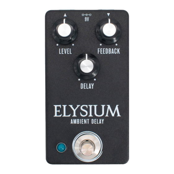
ELYSIUM
BASED ON
®
Ibanez
EM5 Echomachine
EFFECT TYPE
Delay
PROJECT SUMMARY
An analog-voiced digital delay that emulates vintage tape echo units, with heavy filtering and a soft-
clipping overdrive on the repeats.
This documentation is for the kit version of the project. If you purchased the PCB by itself, please
use the
PCB-only version
are completely different due to the specialized parts and assembly methods used in the kit.
Additionally, this is rated as an advanced project. Not only are there a lot of components packed
closely together, it also requires calibration for proper operation. Read all the instructions,
particularly the calibration step on pages 25-26, and make sure you know what skills are needed
before you begin. If you've never built a pedal before, we recommend starting with a different kit.
ELYSIUM AMBIENT DELAY
IMPORTANT NOTE
of the documentation instead. The circuit is the same, but the instructions
BUILD DIFFICULTY
Advanced
DOCUMENT VERSION
1.0.0 (2024-01-26)
1
Advertisement
Table of Contents

Related Manuals for aion ELYSIUM


Summary of Contents for aion ELYSIUM
- Page 1 Read all the instructions, particularly the calibration step on pages 25-26, and make sure you know what skills are needed before you begin. If you’ve never built a pedal before, we recommend starting with a different kit. ELYSIUM AMBIENT DELAY...
-
Page 2: Table Of Contents
23 Enclosure Layout: Input/Output PCB 24 Testing & Assembly 25 Calibration 26 Calibration (Cont.), Final Assembly, and Usage 27 Schematic 28 Full Parts List 29 Troubleshooting Information 30 Support & Resale Terms 31 Legal Information & Document Revisions ELYSIUM AMBIENT DELAY... -
Page 3: Introduction
INTRODUCTION If this is your first pedal, welcome to the hobby and thank you for choosing Aion FX. You’ve just joined a community of over 40,000 people around the world with a passion for building homemade noise machines using obsolete electronics technologies, and we’re glad to have you! If you’ve done this before, it’s great to see you again and we’re confident you’ll find this build experience... - Page 4 68n (0.068) 100n (0.1) Electrolytic Capacitors NAME 10uF 47uF 100uF 100k MLCC Capacitors 390k NAME 470k 47pF 470pF Diodes 680pF NAME 100n (marked “104”) 1N5817 1N914 Transistors NAME Trimmers 2N5087 NAME 2N5088 10k trimmer 78L05 regulator 50k trimmer ELYSIUM AMBIENT DELAY...
- Page 5 Outer washer, potentiometer, 0.475" Other NAME LED bezel LED, blue DC jack Input/output jack Mounting nut, jack, 0.54" Outer washer, jack, 0.6" Lock washer, jack, 0.5" (thin) Enclosure Enclosure screws PCB, main circuit PCB, footswitch PCB, input/output/DC ELYSIUM AMBIENT DELAY...
-
Page 6: Tools Needed
The tip should used to tighten the dress nut to avoid lot of pedals! be no more than 0.1” (2.5mm) wide. scratching or denting it (which can happen with metal tools). ELYSIUM AMBIENT DELAY... -
Page 7: Component Identification
IC SOCKET TRANSISTOR OR JFET Charge pumps and delay chips Some voltage regulators also look like this. They may also look like this. have more than 8 legs. WIRE ASSEMBLY WIRE ASSEMBLY HEADER DC JACK LED BEZEL ELYSIUM AMBIENT DELAY... -
Page 8: Hardware Identification
MOUNTING NUT DRESS NUT LOCK WASHER DIAMETER: 0.36” / 9.1mm DIAMETER: 0.375” / 9.5mm DIAMETER: 0.4” / 10.1mm FOOTSWITCH MOUNTING NUT DRESS NUT LOCK WASHER DIAMETER: 0.6” / 15.2mm DIAMETER: 0.77” / 19.6mm DIAMETER: 0.6” / 15.2mm ELYSIUM AMBIENT DELAY... -
Page 9: Overview
6. Transistors 7. Electrolytic capacitors Not all of these component types are included in each kit, so skip them if they aren’t applicable. Some types of film capacitors are taller than electrolytics, so those can be done last. ELYSIUM AMBIENT DELAY... -
Page 10: Resistors
Turn the board upside-down to keep the components held in place while you solder. Don’t try to do all of the resistors at once. You’ll want to stop periodically flip the board and solder everything, then cut the leads using the wire snippers to make room for more. ELYSIUM AMBIENT DELAY... -
Page 11: Diodes
VALUE 1N5817 1N914 1N914 Next, you’ll populate the diodes. Diodes are polarized, so make sure to identify the polarity band (which indicates the “cathode”, or negative side) and match the band to the footprint on the PCB. ELYSIUM AMBIENT DELAY... -
Page 12: Sockets & Ics
ICs may have two different orientation marks: either a dot in the upper-left or a half-circle notch in the middle of the top side. Some ICs have both marks. This shows which way the IC should be rotated when inserting it into a socket (the socket also has a half-circle notch). ELYSIUM AMBIENT DELAY... -
Page 13: Resistors (Under Ic3 Socket)
These are saved until after the socket because there’s not a lot of extra space, and it’s possible to install them at a slight angle that could prevent the socket from fitting correctly if they go in first. However, if they’re done after the socket then everything will fit in without any trouble. ELYSIUM AMBIENT DELAY... -
Page 14: Trimmers
These trimmers will be used for the calibration process on pages 25 and 26 and should not be adjusted once this is completed. For now, set all three of them them to the 50% position (12:00 noon). ELYSIUM AMBIENT DELAY... - Page 15 Once installed, bend the two outer legs to hold it in place on the board. Be very careful of the orientation since the four parts face in three different directions. Then, solder them in place and clip the leads. ELYSIUM AMBIENT DELAY...
-
Page 16: Capacitors (Non-Polarized)
C3, C4, C9, C18, and C23 are blue MLCCs taped to cardboard. The value is written on the cardboard. C13, C14, C27 and C32 (100n MLCCs) are always yellow. It can be hard to read the code since it’s so small, so it’s easier to identify these two by color. ELYSIUM AMBIENT DELAY... -
Page 17: Wire Headers
They do fit pretty tightly in the holes, though, so press firmly. There’s also a 4-pin header on the I/O board that we will do in a later step. ELYSIUM AMBIENT DELAY... -
Page 18: Capacitors (Polarized)
The longer leg is positive and fits in the square pad. These are the last of the on-board components. Now is the time to go back to page 12 and insert the ICs into the sockets. ELYSIUM AMBIENT DELAY... -
Page 19: Footswitch Pcb
BLUE MARKING Once all three wire assemblies are soldered, set the footswitch PCB aside. We’ll solder the actual footswitch and LED in a later step. ELYSIUM AMBIENT DELAY... -
Page 20: Input/Output Pcb
PCB. There’s not a lot of clearance between the bottom of this board and the top of the main PCB once everything is in place, and you don’t want the pins to short against anything on accident. ELYSIUM AMBIENT DELAY... -
Page 21: Enclosure Layout: Panel Mounts
You’ll need to hold the bezel in place when OUTER WASHER tightening the nut. Be aware that the bezel is fairly MOUNTING NUT sharp. Try using a rubber band for grip instead of just pressing your finger against the bottom. ELYSIUM AMBIENT DELAY... -
Page 22: Enclosure Layout: Main & Footswitch Pcbs
However, Aion FX projects are designed to be extremely easy to remove from the enclosure for troubleshooting, with no desoldering required—so with these kits, it’s actually much easier to “box it before you rock it”. -
Page 23: Enclosure Layout: Input/Output Pcb
Note the use of two mounting nuts on each of the jacks, one inside and one outside. The inner nut acts as a spacer to set the DC jack flush with the outside of the enclosure. The inner nuts should be threaded as far down as they can go. MOUNTING NUT OUTER WASHER LOCK WASHER MOUNTING NUT 125B ELYSIUM AMBIENT DELAY... -
Page 24: Testing & Assembly
Don’t over-tighten or you could damage the set screw. But on the other hand, if it’s not tight enough then the knob will be prone to falling off or losing its alignment with the markings on the enclosure. ELYSIUM AMBIENT DELAY... -
Page 25: Calibration
These are both well within normal operating range, so this behavior won’t normally make a difference. But if you’ve just barely trimmed out the artifacts and you notice they reappear once the unit warms up, then just trim them out again and they should stay out this time. ELYSIUM AMBIENT DELAY... - Page 26 29 for troubleshooting info. USAGE The Elysium has three controls: • Delay (called “Speed” on the EM5) sets the delay time, going from short to long as you turn it up. • Feedback (called “Repeat” on the EM5) sets the number of repeats. Due to the heavy filtering in the delay path, each repeat has degraded sound quality, especially the treble content, resulting in an ambient wash that doesn’t conflict with the dry signal.
-
Page 27: Schematic
XOUT OP1-OUT D1-REQ OP1-IN D2-SCK 2N5088 2N5088 100n D3-DATA 100n D4-IDSW TEST 680pF OP2-IN EASY OP2-OUT SLEEP LPF2-IN DGND 1N914 LPF2-OUT AGND M65831AP D.GND 2N5087 47uF 100n 100n IC2A LM833N IC4A IC4F IC4E SN74HCU04 SN74HCU04 SN74HCU04 D.GND ELYSIUM AMBIENT DELAY... -
Page 28: Full Parts List
100n film 100n film IC4-S DIP-14 socket Diodes Transistors Potentiometers Trimmers PART VALUE PART VALUE PART VALUE PART VALUE 1N5817 2N5088 Feedback 100kB 10k trimmer 1N914 2N5089 Delay 50kB 50k trimmer 1N914 2N5089 Level 100kB 50k trimmer 78L05 ELYSIUM AMBIENT DELAY... -
Page 29: Troubleshooting Information
Record these voltages and include them when posting troubleshooting threads as described on the next page. We will add target voltages to this document soon, but as of the initial release of the kit we don’t have them ready. ELYSIUM AMBIENT DELAY... - Page 30 “goop” the PCB or otherwise obscure the source. In other words: you don’t have to go out of your way to advertise the fact that you use Aion FX kits, but please don’t go out of your way to hide it.
- Page 31 These kits are intended to be built by the customer. Aion FX is not responsible for language that may be used by the customer in the marketing or resale of the finished product.
Need help?
Do you have a question about the ELYSIUM and is the answer not in the manual?
Questions and answers