Table of Contents
Advertisement
Quick Links
PROJECT NAME
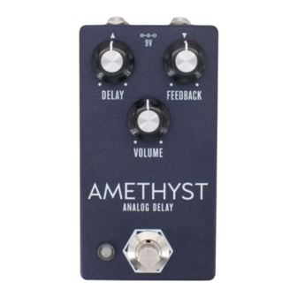
AMETHYST
BASED ON
®
BOSS
DM-2 Delay
EFFECT TYPE
Delay
PROJECT SUMMARY
One of the earliest analog delay effects to use a bucket brigade chip, and still widely considered among
the best analog delays ever designed.
This documentation is for the kit version of the project. If you purchased the PCB by itself, please
use the
PCB-only version
are completely different due to the specialized parts and assembly methods used in the kit.
AMETHYST ANALOG DELAY
IMPORTANT NOTE
of the documentation instead. The circuit is the same, but the instructions
BUILD DIFFICULTY
Advanced
DOCUMENT VERSION
1.0.0 (2024-06-01)
1
Advertisement
Table of Contents

Related Manuals for aion AMETHYST


Summary of Contents for aion AMETHYST
- Page 1 This documentation is for the kit version of the project. If you purchased the PCB by itself, please use the PCB-only version of the documentation instead. The circuit is the same, but the instructions are completely different due to the specialized parts and assembly methods used in the kit. AMETHYST ANALOG DELAY...
-
Page 2: Table Of Contents
24 Testing & Assembly 25 Calibration 26 Calibration (cont.) 27 Final Assembly & Usage 28 Schematic 29 Full Parts List 30 Full Parts List (cont.) 31 Troubleshooting Information 32 Support & Resale Terms 33 Legal Information & Document Revisions AMETHYST ANALOG DELAY... -
Page 3: Introduction
INTRODUCTION If this is your first pedal, welcome to the hobby and thank you for choosing Aion FX. You’ve just joined a community of over 40,000 people around the world with a passion for building homemade noise machines using obsolete electronics technologies, and we’re glad to have you! If you’ve done this before, it’s great to see you again and we’re confident you’ll find this build experience... - Page 4 NAME NAME 1N5817 10uF 1N914 47uF 1N4739A 220uF Trimmers MLCC Capacitors NAME NAME 10k (marked “103”) 100pF (marked “101”) 22k (marked “223”) 330pF (marked “331”) 1M (marked “105”) 100n (marked “104”) 220n (marked “224”) Transistors NAME 2N5088 AMETHYST ANALOG DELAY...
- Page 5 Outer washer, jack, 0.6" Wiring Lock washer, jack, 0.5" (thin) NAME Enclosure Enclosure screws 3-strand wire assembly, 70mm PCB, main circuit 4-strand wire assembly, 122mm PCB, footswitch 3-pin wire assembly header PCB, input/output/DC 4-pin wire assembly header AMETHYST ANALOG DELAY...
-
Page 6: Tools Needed
The tip should used to tighten the dress nut to avoid lot of pedals! be no more than 0.1” (2.5mm) wide. scratching or denting it (which can happen with metal tools). AMETHYST ANALOG DELAY... -
Page 7: Component Identification
Some voltage regulators The pins will be soldered to the also look like this. They may also look like this. adapter during kit assembly. have more than 8 legs. WIRE ASSEMBLY WIRE ASSEMBLY HEADER DC JACK LED BEZEL AMETHYST ANALOG DELAY... -
Page 8: Hardware Identification
MOUNTING NUT DRESS NUT LOCK WASHER DIAMETER: 0.36” / 9.1mm DIAMETER: 0.375” / 9.5mm DIAMETER: 0.4” / 10.1mm FOOTSWITCH MOUNTING NUT DRESS NUT LOCK WASHER DIAMETER: 0.6” / 15.2mm DIAMETER: 0.77” / 19.6mm DIAMETER: 0.6” / 15.2mm AMETHYST ANALOG DELAY... -
Page 9: Overview
6. Transistors 7. Electrolytic capacitors Not all of these component types are included in each kit, so skip them if they aren’t applicable. Some types of film capacitors are taller than electrolytics, so those can be done last. AMETHYST ANALOG DELAY... -
Page 10: Resistors
Turn the board upside-down to keep the components held in place while you solder. Don’t try to do all of the resistors at once. You’ll want to stop periodically flip the board and solder everything, then cut the leads using the wire snippers to make room for more. AMETHYST ANALOG DELAY... -
Page 11: Diodes
D3 (1N914) is the two smaller orange and black one. The larger orange and black one is Z1, the 1N4739A. D2 is not used in the kit. When trimming the leads after soldering, set aside the two leftover leads from the 1N914 diode. We will use these in the next step. AMETHYST ANALOG DELAY... -
Page 12: Jumpers
If you want to be extra careful, you can use your multimeter in continuity test mode to ensure that there is no connection between the two vertical pairs of pads before moving onto the next step. AMETHYST ANALOG DELAY... -
Page 13: Sockets & Ics
IC is in place, but all 14 pins should be soldered as normal. Two of the rows will be used as later as test points for calibration. AMETHYST ANALOG DELAY... - Page 14 For now, set all three of them them to the 50% position (12:00 noon). Note that since they are rotated 90 degrees on the PCB, the 12:00 position means that the indicator points directly to the left. AMETHYST ANALOG DELAY...
-
Page 15: Transistors
Now we’ll do the four transistors. For each, if the legs are not already bent into 0.1” spacing, use your needle-nose pliers to bend the outer two legs as shown. Once installed, bend the two outer legs to hold it in place on the board. Then, solder them in place and clip the leads. AMETHYST ANALOG DELAY... -
Page 16: Capacitors (Non-Polarized)
All of the MLCCs except C8 and C37 are blue MLCC capacitors taped to cardboard. For these, the value will be written on the cardboard. C8 and C37 (100n MLCCs) are the only yellow ones and are most easily identified by color. AMETHYST ANALOG DELAY... -
Page 17: Wire Headers
They do fit pretty tightly in the holes, though, so press firmly. There’s also a 4-pin header on the I/O board that we will do in a later step. AMETHYST ANALOG DELAY... -
Page 18: Capacitors (Polarized)
The longer leg is positive and fits in the square pad. These are the last of the on-board components. Now is the time to go back to page 13 and insert the ICs into the sockets. AMETHYST ANALOG DELAY... -
Page 19: Footswitch Pcb
BLUE MARKING Once all three wire assemblies are soldered, set the footswitch PCB aside. We’ll solder the actual footswitch and LED in a later step. AMETHYST ANALOG DELAY... -
Page 20: Input/Output Pcb
PCB. There’s not a lot of clearance between the bottom of this board and the top of the main PCB once everything is in place, and you don’t want the pins to short against anything on accident. AMETHYST ANALOG DELAY... -
Page 21: Enclosure Layout: Panel Mounts
You’ll need to hold the bezel in place when OUTER WASHER tightening the nut. Be aware that the bezel is fairly MOUNTING NUT sharp. Try using a rubber band for grip instead of just pressing your finger against the bottom. AMETHYST ANALOG DELAY... -
Page 22: Enclosure Layout: Main & Footswitch Pcbs
However, Aion FX projects are designed to be extremely easy to remove from the enclosure for troubleshooting, with no desoldering required—so with these kits, it’s actually much easier to “box it before you rock it”. -
Page 23: Enclosure Layout: Input/Output Pcb
Note the use of two mounting nuts on each of the jacks, one inside and one outside. The inner nut acts as a spacer to set the DC jack flush with the outside of the enclosure. The inner nuts should be threaded as far down as they can go. MOUNTING NUT OUTER WASHER LOCK WASHER MOUNTING NUT 125B AMETHYST ANALOG DELAY... -
Page 24: Testing & Assembly
Don’t over-tighten or you could damage the set screw. But on the other hand, if it’s not tight enough then the knob will be prone to falling off or losing its alignment with the markings on the enclosure. AMETHYST ANALOG DELAY... -
Page 25: Calibration
CALIBRATION The Amethyst circuit has three different trimmers that need to be adjusted for best performance and minimal noise. While the calibration is best done with professional test equipment, it can be done by ear as well, and we have included instructions for both. -
Page 26: Calibration, Cont
4. Adjust the CANCEL trimmer until the two clock signals have converged with the closest amount of overlap. Now, test all three knobs across the full range. If you notice any distortion, artifacts, or squealing, you’ll need to go through the calibration steps again. AMETHYST ANALOG DELAY... -
Page 27: Final Assembly & Usage
USAGE The Amethyst has three controls: • Delay (called “Repeat Rate” on the DM-2) sets the delay time, longest at minimum and getting shorter as you turn it up. It seems backwards, but it matches the rotation on the original DM-2. -
Page 28: Schematic
2N5088 330pF IC1A JRC4558D 2N5088 IC2A v571 OMIT 10uF 220n GND GND IC1B JRC4558D 100pF 470R 100pF OUT1 OUT2 10uF GND2 GND2 v3205 GND2 2N5088 2N5088 330pF 100n OMIT v3102 IC2B v571 GND2 GND2 GND2 100pF 220n AMETHYST ANALOG DELAY... -
Page 29: Full Parts List
10uF electro 1uF electro 10uF electro 47uF electro 10uF electro 10uF electro 220n MLCC 220uF electro 100n MLCC 100pF MLCC 100pF MLCC 220uF electro 220n MLCC 1uF electro 1uF electro 100n MLCC 100pF MLCC 2n2 film 100n film AMETHYST ANALOG DELAY... -
Page 30: Full Parts List, Cont
PART VALUE PART 2N5088 1N5817 JRC4558D DIP-8 socket (4) 2N5088 1N914 v571D DIP-14 socket 2N5088 1N4739A v3205SD 2N5088 v3102D Trimmers Potentiometers Switches PART VALUE PART VALUE PART CANCEL Delay 3PDT stomp BIAS Feedback 50kB CLOCK Volume 50kB AMETHYST ANALOG DELAY... -
Page 31: Troubleshooting Information
4.67 1.85 1.84 4.56 4.67 3.03 1.85 5.42 9.35 1.85 2.32 8.31 VOLTAGE VOLTAGE VOLTAGE 8.85 9.35 9.35 4.56 4.15 3.00 0.63 3.74 2.43 4.58 4.71 VOLTAGE VOLTAGE 4.67 4.70 9.35 9.35 8.32 6.11 5.50 5.53 4.92 AMETHYST ANALOG DELAY... - Page 32 “goop” the PCB or otherwise obscure the source. In other words: you don’t have to go out of your way to advertise the fact that you use Aion FX kits, but please don’t go out of your way to hide it.
- Page 33 These kits are intended to be built by the customer. Aion FX is not responsible for language that may be used by the customer in the marketing or resale of the finished product.
Need help?
Do you have a question about the AMETHYST and is the answer not in the manual?
Questions and answers