
Related Manuals for SensorLink Voltstik


Summary of Contents for SensorLink Voltstik
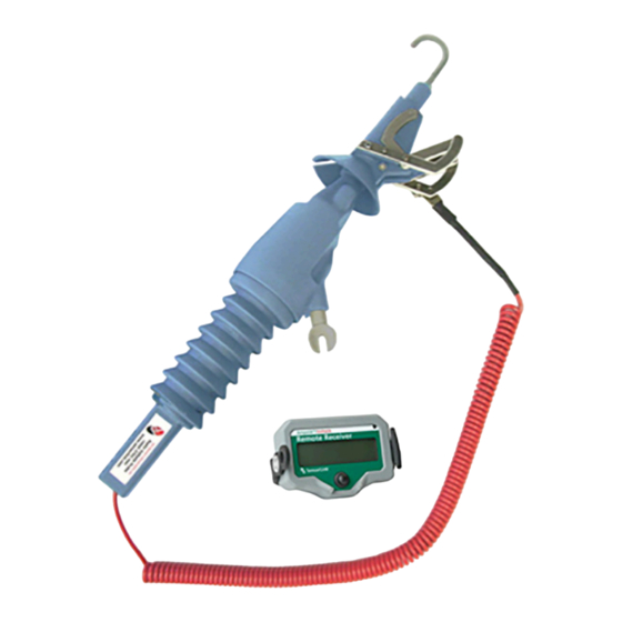
- Page 1 Operators Manual True RMS Voltstik Radio Linked Multiple Reading Voltmeter Region One Region Two Region Three SensorLink ...
- Page 3 Radio Voltstik Overhead Radio Voltstik Underground...
-
Page 4: Table Of Contents
Operators Manual True RMS Radio Voltstik Radio Linked Multiple Reading Voltmeter Available Stock Codes: 8-13302-50HZ 8-13302-50HZ-EU 8-13302-50HZ-868 8-13302-60HZ 8-13302-60HZ-868 8-121RAV 8-121RAV EU 8-121RAV 868 Table of Contents Page Safety Information Theory of Operation FCC Statements Specifications Voltstik Receiver Display Functions... -
Page 5: Safety Information
The cover plate, chuck, probe section, resistor section, and entire Radio Voltstik Transmitter are to be considered at the same potential. Putting the cover plate, chuck, or other parts of the Radio Voltstik within the air gap of adjacent phases or ground could cause a phase to phase or phase to ground fault. -
Page 6: Theory Of Operation
THEORY OF OPERATION The True RMS Radio Voltstik has been developed specifically for measurement of AC voltages for P-P and P-G measurements on both Overhead and Underground distribution circuits with 0 - 37,000 Volts. The True RMS feature allows accurate measurement of voltage even when the nominal waveform is distorted or when harmonics are present. -
Page 7: Fcc Statements
1. L’appareil ne doit pas produire de brouillage; 2. L’appareil doit accepter tout brouillage radioélectrique subi, même si le brouillage est susceptible d’en compromettre le fonctionnement. Declaration of Conformity TRADE NUMBER: SensorLink Corporation MODEL NUMBER: 8-121RAV COMPLIANCE TEST REPORT NUMBER: 106048... -
Page 8: Specifications
SPECIFICATIONS Kit Number 6-133 Kit (Includes both 8-13302 Voltstik & 8-121RAV Receiver) Range of Operation Voltage 0 - 37kV 0 - 15 kV (Underground with bushing adapter) Frequency 50Hz Calibrated 47 to 53Hz 60Hz Calibrated 57 to 63Hz Resolution 1 Volt Accuracy ±... -
Page 9: Voltstik Receiver Display Functions
Radio Voltstik Transmitter. The receiver will display “noSiG” until the radio in the Transmitter communicates to it. The receiver is designed to operate with both the Radio Ampstik as well as the Voltstik. RUN Mode (Default Mode) The reading continuoulsy changes as the voltage changes. - Page 10 Receiver Display: Press and hold the control switch on the Receiver Display and scroll to the OFF option. Release the control switch. Voltstik Transmitter: Press and hold the control switch until the LED goes to solid GREEN. Release the control switch.
- Page 11 Backlight The Receiver Display is designed to automatically power on when the ambient light is low. This helps users view the display in low-light situations. The light sensor is located on the front of the unit. The user may see some flicker if the backlight is on when under artificial lighting. By default, the unit will start in Auto on/off mode on each power on.
-
Page 12: Voltstik Operation Instructions
Step 3: Attaching the hot stick. Attach the Voltstik to a universal hot stick. Tighten the bolt to make sure the instrument is well secured to the hot stick. - Page 13 Step 5: Connecting to the neutral. Guide the base of the arms on the AutoClamp to the cable, neutral or ground, and force the conductor to apply pressure to the moving arms of the clamp. The moving arms of the clamp should quickly close making a secure connection with the cable.
- Page 14 Only approach the phase you are intending to measure. Make sure all parts of the Voltstik stay out of the air gap that surrounds the adjacent phases. Failure to do so could result in damage to the instrument and/or a phase to phase fault, endangering the user and surroundings.
- Page 15 Step 10: Removing the AutoClamp. When your last measurement has been held, remove the Probe from the phase and return to the AutoClamp. Place the hook of the Probe so it will slide directly up into the AutoClamp. Push the Probe all the way into the clamp;...
-
Page 16: Phase To Phase Measurements
Step 3: Attaching the hot stick. Attach the Voltstik to a universal hot stick. Tighten the bolt to make sure the instrument is well secured to the hot stick. - Page 17 Step 5: Connecting to the Reference Phase. Using the hot stick, approach the phase with the instrument. Guide the base of the arms on the AutoClamp to the cable and force the conductor to apply pressure to the moving arms of the clamp. The moving arms of the clamp should quickly close, making a secure connection with the cable.
- Page 18 Only approach the phase you are intending to measure. Make sure all parts of the Voltstik stay out of the air gap that surrounds the adjacent phases. Failure to do so could result in damage to the instrument and/or a phase to phase fault, endangering the user and surroundings.
- Page 19 Step 10: Removing the AutoClamp. When your last measurement has been held, remove the Probe from the phase and return to the AutoClamp. Place the hook of the Probe so it will slide directly up into the AutoClamp. Push the Probe all the way into the clamp;...
-
Page 20: Phase To Ground Measurements On
Optional equipment required. Contact SensoLink for order details Step 1: Setting up the Voltstik with bushing probe Remove the hook from the Voltstik Probe and screw the Bushing Probe onto the end of the Voltstik Probe Step 2: Setting up the Voltstik clamp adaptor •... - Page 21 Press the Auto Clamp onto an exposed bare ground wire, or if able to securely clamp the Extension Cable directly to the bare grounded cable* • Rotate the Voltstik and release it from the Auto Clamp • Insert the Bushing Probe into the bushing Step 4: Recovering the AutoClamp •...
-
Page 22: High Voltage Operation
There are no special considerations for transporting the device. Battery Replacement The Voltstik transmitter and display are powered by a two 9V batteries, one in each unit. When the“LO BAT” indication shows on the Receiver Display, the batteries in the Receiver Display should be replaced. - Page 23 Ultralife batteries are sold. Cleaning & Preventative Maintenance The SensorLink Radio Voltstik is an electronic meter, built to be used in the harsh conditions of high voltage environments. To ensure its continued lifetime use, clean and dry the entire meter before storing in the carrying case, do not drop the meters, do not alter the units in any manner, and visually inspect for cracks in the housing.
-
Page 24: Troubleshooting The Voltstik
In the volt/amp menu, change the selection from VA-On (which automatically selects the mode) to V-On, which will manually put the Receiver Display in volt mode. Service and Repair Questions Please contact SensorLink or an authorized agent for the return process of product for evaluation, repair, calibration, and verification. SensorLink Corporation... -
Page 25: Warranty
What SensorLink Will Do: If a defect in materials or workmanship or shipping damages as described above occurs within the warranty period, SensorLink will, at its election, repair or replace the Product at no charge or provide a refund. What This Warranty Does Not Cover:... - Page 26 If the inspection uncovers a defect, SensorLink will repair or replace the Product and pay for the cost of shipping the Product back to you. Alternatively, SensorLink may issue you a refund of your original purchase price.
-
Page 28: Quality Assurance
I hereby certify that the True RMS Voltmeter listed above has passed all tests defined in the SensorLink standard. I also certify that I have reviewed the standard and test procedure and that they are sufficient in determining compliance with the standard.
Need help?
Do you have a question about the Voltstik and is the answer not in the manual?
Questions and answers