Table of Contents
Advertisement
Quick Links
Advertisement
Table of Contents

Related Manuals for SensorLink Ampstik+


Summary of Contents for SensorLink Ampstik+
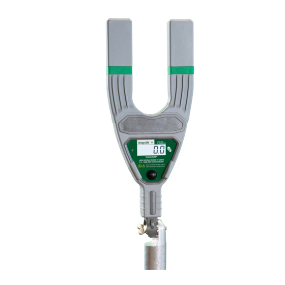
- Page 1 Operators Manual ® Ampstik Slip-on Ammeters SensorLink ...
- Page 2 Pad-mounted current measurement ® Ampstik +, Model 8-024-PLUS, Wide Jaw Sensor Opening Overhead current measurement ® Ampstik +, Model 8-020-XT PLUS, Standard Sensor Opening...
-
Page 3: Table Of Contents
Operators Manual Ampstik ® Slip-on Ammeters Available Stock Codes: 8-020-XT PLUS 50HZ 8-020-XT PLUS 60HZ 8-020-XT PLUS EURO 8-020-XT PLUS FRG 8-024-PLUS-50HZ 8-024-PLUS-60HZ 8-024-PLUS-EURO Table of Contents Page Specifi cations Safety Warnings Theory of Operation Taking a Measurement: RUN Mode Taking a Measurement: HOLD Mode Display Resolution Powering the unit OFF... -
Page 4: Specifications
SPECIFICATIONS Model Number 8-020-XT Plus 8-024-Plus Range of Operation Voltage Phase to Phase 0-500 kV 0-500 kV Current 0.5-5000 A 0.5-5000 A Sensor Opening Standard Wide Jaw Opening Width 2.5 in, 6.35 cm 4 in, 10.16 cm Dimensions 13.96 in x 5.5 in x 1.92 in 17.04 in x 8.95 in x 1.93 in 35.46 cm x 13.97 cm x 4.88 cm 43.28 cm x 22.73 cm x 4.9 cm... -
Page 5: Safety Warnings
Safety Information Read all safety and instruction statements before using the product. Failing to follow the safety guidelines can cause severe injury or death. Ampstik+ units are designed for use on live, overhead lines with 0 to 500KV. All procedures ap pro pri ate for the line voltage are to be taken, including proper work techniques, equipment, and Personal Protection Equipment. -
Page 6: Taking A Measurement: Run Mode
Take a Measurement in RUN Mode When in RUN MODE, the reading continuously changes as the current on the conductor changes. The unit is immediately in the RUN mode after powering on. To place the instrument into the RUN mode from a different mode, press and hold the control switch and scroll to the option RUN, then release the control switch to engage the option. - Page 7 Step 3: Take a measurement. Place the Ampstik+ on the conductor as shown below, with the conductor positioned anywhere below the measurement lines on the arms of the unit. If the conductor cannot be placed below the bump-outs, readings are taken but the accuracy may be lessened. Step 4: Observe the readings being displayed on the unit.
-
Page 8: Taking A Measurement: Hold Mode
Take a Measurement in HOLD Mode When in HOLD mode, the unit will automatically measure and hold up to four unique current readings Step 1: Attach the unit to a hot stick with a universal chuck adapter. Step 2: Power on the unit by pressing and releasing the control switch. STARTUP TEST The Ampstik+ conducts a startup test to verify the sensor and circuitry is functioning correctly. - Page 9 Step 4: Take a measurement. Place the Ampstik+ on the conductor as shown below, with the conductor positioned anywhere below the measurement lines on the arms of the unit. If the conductor cannot be placed below the measurement line, readings are taken but the accuracy may be lessened. Step 5: Hold the unit on the conductor for 2-4 seconds and then remove from the line.
-
Page 10: Display Resolution
Display Resolution of the Measurements The unit will display to .1A in RUN mode and .3A in HOLD mode. The display resolution changes on the following ranges: XX.X 0-99.9Amps 0.1Amp resolution XXXX 100 to 1999 Amps 1Amp resolution 2000 to 5000 Amps X.XX 2.00 kAmps 10 Amp resolution (2 decimal places... -
Page 11: Backlight Operation
Backlight The Backlight on the Ampstik+ is designed to automatically power on when the ambient light is low. This helps users view the display in low-light situations. The light sensor is located on the front of the unit. The user may see some fl icker if the backlight is on when under artifi cial lighting By default, the Ampstik+ will start in Auto on/off mode on each power on. -
Page 12: Battery Replacement
Battery Replacement The Ampstik+ is powered by a single 9V battery. The battery should be re placed when the “LO BAT” indication shows on the display. To change the battery, loosen the screw on the battery cover at the rear of the unit. Pull the battery out of the compartment and install a fresh battery. -
Page 13: Troubleshooting
Fail Codes The unit will not enter into measurement mode if the self-test has any of the below failures. The unit will need to be returned to SensorLink for repair evaluation. FAIL CODE "1": Break to the main current sensor FAIL CODE "2": Break to a current sensor component... -
Page 14: Warranty
What SensorLink Will Do: If a defect in materials or workmanship or shipping damages as described above occurs within the warranty period, SensorLink will, at its election, repair or replace the Product at no charge or provide a refund. What This Warranty Does Not Cover:... - Page 15 Ferndale, WA 98248 (360) 595-1000 SensorLink will begin its inspection of the Product within fi ve (5) business days of receipt and will contact you when its inspection is complete. If the inspection uncovers a defect, SensorLink will repair or replace the Product and pay for the cost of shipping the Product back to you.
-
Page 16: Quality Assurance
True RMS Ammeter Models 8-020-XT Plus, 8-024-Plus SensorLink certifi es that its calibration measurements are trace able to the National Institute of Standards and Tech nol o gy (NIST), to the extent allowed by the Institute's cal i bra tion fa cil i ty, and to the calibration facilities of other In ter na tion al Standards Or ga ni za tion members.
Need help?
Do you have a question about the Ampstik+ and is the answer not in the manual?
Questions and answers