Table of Contents
Advertisement
Quick Links
Installation and Operation Manual
Wireless Transceiver (TRV)
For Platinum Controls with Communication
WARNING
This equipment complies with the limits for a Class B digital device, pursuant to Part 15 of the FCC rules. These limits are designed to provide
reasonable protection against harmful interference in a residential installation. This equipment generates, uses, and can radiate radio
frequency energy and if not installed and used in accordance with the instructions, may cause harmful interference to radio communications.
If this equipment does cause harmful interference to radio or television reception, which can be determined, by turning this equipment OFF
and ON, the user may correct the interference by: (1) Reorienting or relocating the receiving antenna, (2) Increasing separation between the
equipment and wireless components, (3) Connecting the equipment to a different outlet circuit from that of the wireless components, or
(4) Consulting an experienced radio/TV technician for assistance.
059052-00 Rev. F
Advertisement
Table of Contents

Related Manuals for heat-timer TRV

Summary of Contents for heat-timer TRV
- Page 1 Installation and Operation Manual Wireless Transceiver (TRV) For Platinum Controls with Communication WARNING This equipment complies with the limits for a Class B digital device, pursuant to Part 15 of the FCC rules. These limits are designed to provide reasonable protection against harmful interference in a residential installation. This equipment generates, uses, and can radiate radio frequency energy and if not installed and used in accordance with the instructions, may cause harmful interference to radio communications.
-
Page 2: Table Of Contents
2 Wireless Transceiver Installation and Operation Manual Contents Controls, Indicators, and Connections. . . . . . . . . . . . . . . . . . . . . 3 Specifications . . . . . . . . . . . . . . . . . . . . . . . . . . . . . . . . . . . . . . . . . 4 Wireless Transceiver (TRV) . . . . . . . . . . . . . . . . . . . . . . . . . . 4 Outdoor Antenna. . . . . . . . . . . . . . . . . . . . . . . . . . . . . . . . . . 4 Installation Instructions . . . . . . . . . . . . . . . . . . . . . . . . . . . . . . . . 5 Required Materials (Not Supplied) . . . . . . . . . . . . . . . . . . . . . 5 Programming the Wireless TRV System ID. . . . . . . . . . . . . . . 5 Clearing the Wireless TRV System ID . . . . . . . . . . . . . . . . 7 Mounting the Wireless TRV . . . . . . . . . . . . . . . . . . . . . . . . . . . 8 Mounting the Wireless TRV Transformer. . . . . . . . . . . . . . . . 8 Connecting the Wiring . . . . . . . . . . . . . . . . . . . . . . . . . . . . . . . 9 Power Input Wiring . . . . . . . . . . . . . . . . . . . . . . . . . . . . . . 9 Attaching an External Antenna . . . . . . . . . . . . . . . . . . . . . . . 10 Installing an Indoor Antenna . . . . . . . . . . . . . . . . . . . . . . 10 Installing an Outdoor Antenna (Optional) . . . . . . . . . . . 11 Performing the ICMS Configuration . . . . . . . . . . . . . . . . . . . 11 Detailed Operation . . . . . . . . . . . . . . . . . . . . . . . . . . . . . . . . . . . 12 Control Theory . . . . . . . . . . . . . . . . . . . . . . . . . . . . . . . . . . . . 12 Troubleshooting . . . . . . . . . . . . . . . . . . . . . . . . . . . . . . . . . . . . . . 13 Wireless System Information . . . . . . . . . . . . . . . . . . . . . . . . . . . 14 Notes . . . . . . . . . . . . . . . . . . . . . . . . . . . . . . . . . . . . . . . . . . . . . . . 15 Heat‐Timer Corp. 059052-00 Rev. F... -
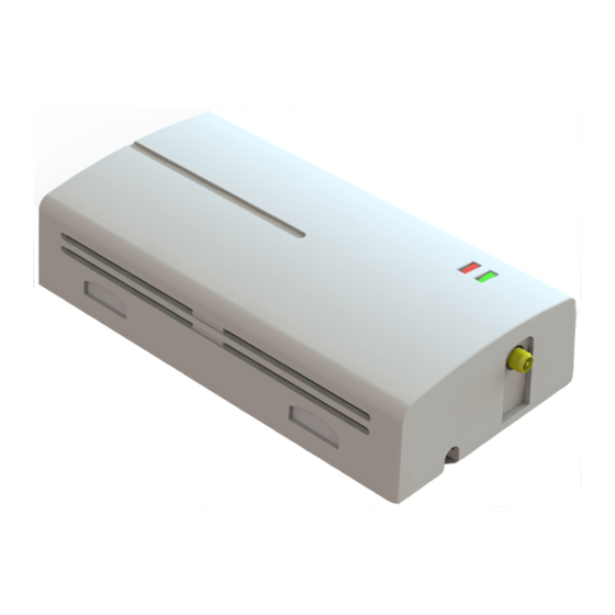
Page 3: Controls, Indicators, And Connections
Controls, Indicators, and Connections 3 Controls, Indicators, and Connections Figure 1: Wireless Transceiver Controls, Indicators, and Connections Item Description Item Description Internal use only. DIP Switch • 4: Auto‐Addressing Switch OFF: Auto‐addressing enabled ON: Auto‐addressing disabled RS485 Connection Status Indicators Programming interface for the Wireless Programmer • Red LED blinks when transmitting data. or MSI Hub. • Green LED blinks when receiving data. If both LEDs are blinking, no System ID has been configured. Received Signal Strength Indicator (RSSI) LEDs External Antenna Connection • 1 LED = Poor • 2 LEDs = Bad • 3 LEDs = Good • 4 LEDs = Great • 5 LEDs = Best Send Packet Button 8Vac Power Input Connection (Primary) When pressed, information is sent to the MSI Hub. Connection for the 8Vac dedicated power transformer. Heat‐Timer Corp. -
Page 4: Specifications
4 Wireless Transceiver Installation and Operation Manual Specifications Wireless Transceiver (TRV) ⅛ ¾ Dimensions (W x H x D): . . . . . . . . . . . . . . . . . . . . . . . . . . . . . . . . . . . . . . . . . . . . . . . . . . 6” x 3 ” x 1 ” (152.4mm x 79.5mm x 44.5mm) Mounting Locations: . . . . . . . . . . . . . . . . . . . . . . . . . . . . . . . . . . . . . . . . . . . . . . . . . . . . . . . . . . . . . . . . . . . . . . . . . . . . Wall or Ceiling Mount Temperature Range: . . . . . . . . . . . . . . . . . . . . . . . . . . . . . . . . . . . . . . . . . . . . . . . . . . . . . . . . . . . . . . . . . . . . . . . . 32°F to 150°F (0°C to 66°C) Power Input: . . . . . . . . . . . . . . . . . . . . . . . . . . . . . . . . . . . . . . . . . . . . . . . . . . . . . . . . . . . . . . . . . . . . . . . . . . . . . .8Vac Transformer (Supplied) Transmission/Reception: . . . . . . . . . . . . . . . . . . . . . . . . . . . . . . . . . . . . . . . . . . . . . . . . . . . . . . . . . . . . . . . . . . . . Internal/External Antenna Frequency: . . . . . . . . . . . . . . . . . . . . . . . . . . . . . . . . . . . . . . . . . . . . . . . . . . . . . . . . . . . . . . . . . . . . . . . . . . . . . . . . . . . . . . . . RF 900MHz FHSS Signal Strength: . . . . . . . . . . . . . . . . . . . . . . . . . . . . . . . . . . . . . . . . . . . . . . . . . . . . . . . . . . . . . . . . . . . . . . . . . . . . . . . . . . . 25mW to 200mW Programming Interface: . . . . . . . . . . . . . . . . . . . . . . . . . . . . . . . . . . . . . . . . . . . . . . . . . . . . . . . . . . . . . . . . . . . . . . . . . . . . . . . . . . . . . . RS485 User Interface: . . . . . . . . . . . . . . . . . . . . . . . . . . . . . . . . . . . . . . . . . . . . . . . . . . . . . . . . . . . . . . . . . . . . . . . . . . . . . . . . Send Packet Button (1) Status Indicators (2 Main LEDs, 5 RSSI LEDs) Outdoor Antenna Frequency: . . . . . . . . . . . . . . . . . . . . . . . . . . . . . . . . . . . . . . . . . . . . . . . . . . . . . . . . . . . . . . . . . . . . . . . . . . . . . . . . . . . . . . . . . . . . . RF 900MHz Rated Wind Velocity:. . . . . . . . . . . . . . . . . . . . . . . . . . . . . . . . . . . . . . . . . . . . . . . . . . . . . . . . . . . . . . . . . . . . . . . . . . . . . . 108 MPH (174 KPH) Mounting: . . . . . . . . . . . . . . . . . . . . . . . . . . . . . . . . . . . . . . . . . . . . . . . . . . . . . . . . Vertically, Outdoors Using Provided Bracket and Adapter Cable Length: . . . . . . . . . . . . . . . . . . . . . . . . . . . . . . . . . . . . . . . . . . . . . . . . . . . . . . . . . . . . . . . . . . . . . . . . . . . . . . . . . . . . 15 feet (4.6 meters) Heat‐Timer Corp. -
Page 5: Installation Instructions
Installation Instructions 5 Installation Instructions The Wireless TRV installation process consists of the following basic steps: 1. Programming the Wireless TRV System ID. 2. Mounting the Wireless TRV. 3. Connecting power wiring. 4. Attaching an external antenna. 5. Configuring the devices. Required Materials (Not Supplied) The following materials/tools are required for installation, but are not supplied: • General tool kit (screwdrivers, wire strippers, power drill, etc.) • 18 AWG cable (Heat‐Timer p/n 703001‐01 or equivalent #18/2 cable) – used for the 8Vac Wireless TRV input power connection Programming the Wireless TRV System ID For the Wireless TRV to function in a network, each TRV must communicate with another nearby TRV or MSI Hub. Each wireless network should have a unique System ID that enables all wireless components with that ID to communicate with each other. 1. Open the Wireless TRV. CAUTION Do not use excessive force when removing the Wireless TRV cover or damage to the equipment will occur. a. Locate the two rectangular locking‐tab slots (1) on the bottom of the Wireless TRV cover. b. Gently press on the rectangular locking‐tab slots so the locking tabs release, and then remove the cover. Heat‐Timer Corp. 059052-00 Rev. F... - Page 6 2. Program the Wireless TRV System ID using one of the following methods: • Program the System ID by Connecting the Wireless TRV to the MSI Hub NOTE: When programming the System ID with the MSI Hub cable, do not connect an external power supply to the TRV. Power must be supplied by the MSI Hub. a. Ensure the MSI Hub has been powered‐on and has already been programmed with the System ID. Observe the MSI Hub status LEDs (1). If the status LEDs are not blinking, or are blinking only once every 15 seconds, a System ID has been programmed. If the LEDs are blinking rapidly (once per second), a System ID has not been programmed. Wireless TRV MSI Hub b. Connect the provided black MSI RJ11 communications cable (2) to the programming connection on the MSI Hub (3) and Wireless TRV (4). CAUTION The black MSI RJ11 communications cable MUST be used when connecting the MSI Hub to the Wireless TRV. Using any other cable may result in damage to the MSI Hub and/or the Wireless TRV. c. Observe the red and green status LEDs (5). When the LEDs stop blinking, the TRV is programmed and ready to install. NOTE: If the red LED remains lit for more than 20 seconds, the Wireless TRV has already been programmed with a System ID. The System ID must be cleared before proceeding. Refer to “Clearing the Wireless TRV System ID” on page 7. d. Disconnect the Wireless TRV from the MSI Hub. Repeat this procedure for any additional Wireless TRVs, and then continue with “Mounting the Wireless TRV” on page 8. • Program the System ID Wirelessly using the MSI Hub a. Ensure the MSI Hub has been powered‐on and has already been programmed with the System ID. Observe the MSI Hub status LEDs (1). If the status LEDs are not blinking, or are blinking only once every 15 seconds, a System ID has been programmed. If the LEDs are blinking rapidly (once per second), a System ID has not been programmed. Wireless TRV MSI Hub Heat‐Timer Corp. 059052-00 Rev. F...
-
Page 7: Clearing The Wireless Trv System Id
Observe the red and green status LEDs (4). When the LEDs stop blinking, the TRV is programmed and ready to install. NOTE: If the red LED remains lit for more than 20 seconds, the Wireless TRV has already been programmed with a System ID. The System ID must be cleared before proceeding. Refer to “Clearing the Wireless TRV System ID” on page 7. e. Disconnect the battery pack from the Wireless TRV. Repeat this procedure for any additional Wireless TRVs. f. After the System ID has been programmed on all Wireless TRVs, press the System ID Set/Reset button on the MSI Hub to return the device to normal operation. g. Continue with “Mounting the Wireless TRV” on page 8. • Manually Program the System ID using the Hand‐Held Wireless Programmer NOTE: Use this procedure to program the System ID in a system that is not self‐addressing. a. On the Wireless TRV, locate the DIP switches (1) and disable auto‐addressing by placing switch 4 in the “on” position. b. Connect the Hand‐Held Wireless Programmer to program the System ID and Net Address. Refer to the Hand‐Held Wireless Programmer manual for information. c. Continue with “Mounting the Wireless TRV” on page 8. Clearing the Wireless TRV System ID NOTE: This procedure is only necessary if installing a Wireless TRV that already has the System ID set. 1. Disconnect power from the Wireless TRV (disconnect the black MSI RJ11 communications cable or the 9V Battery Pack). 2. Press and hold the Send Packet Button (1) on the Wireless TRV. While holding the button, reconnect power to the Wireless TRV. 3. Continue holding the button until the red and green LED start blinking together. The System ID has been cleared. 4. Return to Step 2 on page 6 to reprogram the System ID on the Wireless TRV. Heat‐Timer Corp. 059052-00 Rev. F... -
Page 8: Mounting The Wireless Trv
8 Wireless Transceiver Installation and Operation Manual Mounting the Wireless TRV NOTE: The System ID must be programmed prior to mounting the Wireless TRV. Ensure the steps provided in “Programming the Wireless TRV System ID” on page 5 have been completed before continuing. The Wireless TRV cover should already have been removed 1. Select an appropriate location to mount the Wireless TRV. The location must meet the following minimum requirements: • The mounting surface can be any wall or ceiling, and should be flat and strong enough to hold the weight of the device. • DO NOT mount the device in a location where it will be exposed to heating, cooling, or humidity sources (such as near radiators, heating/cooling vents, windows, doors, or in a kitchen or bathroom. • The ambient temperature of the mounting location should be between 32°F to 150°F (0°C to 66°C). 2. Position the Wireless TRV base (2) in the desired location and connect the 9V Battery Pack (Heat‐Timer p/n 904292‐00) to the RJ11 jack (3) on the Wireless TRV. 3. Observe the RSSI LEDs (4) on the Wireless TRV circuit board to determine the signal strength. At least three LEDs should be lit, indicating “good” signal. If fewer than three LEDs are lit, move the Wireless TRV to a new location closer to the MSI Hub. Repeat this step until an acceptable signal strength is achieved. 4. After a location is found that provides an acceptable signal strength, disconnect the Heat‐Timer Battery Pack from the Wireless TRV, and then secure the TRV base (2) in place using the provided screws through the two mounting holes (5) in the base. NOTE: Do not replace the Wireless TRV cover (1) until all wiring is completed. 5. Repeat this procedure for any additional Wireless TRVs. 6. Continue with “Mounting the Wireless TRV Transformer”. Mounting the Wireless TRV Transformer 1. Select an appropriate location to mount the AC power transformer. The location must meet the following minimum requirements: • The location should be within close proximity of the Wireless TRV to reduce wiring. • The mounting surface should be flat and strong enough to hold the weight of the device. • DO NOT mount the device in a location where it will be exposed to extreme heat, cold, humidity, or moisture. -
Page 9: Connecting The Wiring
Installation Instructions 9 Connecting the Wiring This section covers connecting power to the Wireless TRV. Power Input Wiring WARNING ELECTRICAL SHOCK HAZARD! For your safety, to avoid the risk of electric shock, disconnect electrical power to the device before servicing or making any electrical connections. DO NOT re‐connect electrical power until ALL wiring to the MSI Hub is completed. Failure to do so may result in severe personal injury or death. DO NOT share the Wireless TRV AC power transformer with other devices. This may cause problems with the wireless operation or permanent damage to the equipment. 1. De‐energize the circuit that will provide power to the transformer by turning off the appropriate circuit breaker. 2. Connect the two black wires from the transformer to the incoming Line and Neutral 120Vac input power supply. NOTE: The input power wires must be N.E.C. Class 1. 3. Connect the green wire from the transformer to ground. DO NOT use the Neutral line as the earth ground! 4. Connect the wiring from the two terminals marked “8V 10VA” (left and center terminal) on the low‐voltage side of the transformer to the 8Vac Power Input Connection terminals (1) on the Wireless TRV. NOTE: Use 16 AWG multi‐conductor, unshielded twisted‐pair cable (Belden p/n 8471, 85102, or equivalent #16/2 cable). 5. Replace the Wireless TRV cover. 6. Re‐energize the circuit that will provide power to the Wireless TRV. 7. Continue with “Attaching an External Antenna” on page 10. Heat‐Timer Corp. 059052-00 Rev. F... -
Page 10: Attaching An External Antenna
10 Wireless Transceiver Installation and Operation Manual Attaching an External Antenna The Wireless TRV is supplied with a rubberized external antenna that is intended only for indoor use. The antenna can be rotated around a swivel‐point to change its direction in order to achieve the best possible signal strength. For installations where data transmission covers a large distance, such as between buildings, install and connect an Outdoor Antenna to the Wireless TRV. Refer to “Installing an Outdoor Antenna (Optional)” on page 11. To cover very large distances, use multiple Outdoor Antennas, each connected to a wireless MSI Hub and transceiver. NOTE: To achieve the best reception, the antennas of all wireless devices need to be parallel to each other. Installing an Indoor Antenna CAUTION The Indoor Antenna must be mounted indoors. Mounting the antenna outdoors may result in damage to the equipment. 1. Screw the antenna onto the external antenna connector on the Wireless TRV. 2. Continue with “Performing the ICMS Configuration” on page 11. Heat‐Timer Corp. 059052-00 Rev. F... -
Page 11: Installing An Outdoor Antenna (Optional)
Installation Instructions 11 Installing an Outdoor Antenna (Optional) 1. Find an appropriate mounting location to maximize the signal reception for the Outdoor Antenna. NOTE: To achieve the best reception, all antennas of all wireless devices must be parallel to each other. 2. Securely mount the antenna mast (2” [5cm] O.D. pipe) in the desired location. The mast must be mounted vertically. 3. Place the threaded portion of the antenna base through the hole located in the mounting bracket. Secure the antenna to the mounting bracket using the supplied washer and mounting nut. 4. Attach the mounting bracket to the antenna mast using two U‐bolts and four washers and hex nuts. Ensure the tightened so that the mounting plate does not move. 5. Screw the adapter onto the threaded portion of the antenna base. 6. Attach one end of the antenna cable to the antenna adapter, and then connect the other end of the cable to the external antenna connector on the Wireless TRV. Note that an optional surge suppressor can be attached to the end of the cable before connecting to the TRV Antenna Socket. 7. Continue with “Performing the ICMS Configuration” on page 11. Performing the ICMS Configuration After the Wireless TRVs have been configured and installed, they must be configured in ICMS. 1. Write the location of the Wireless TRV on the ID card provided with the device (for example, Apt. 5A). 2. Access www.HTControls.com and log in. 3. Configure ICMS with the applicable Wireless TRV installation data (device ID, name, type, and location). 4. After the ICMS configuration is complete, log out of ICMS. Heat‐Timer Corp. 059052-00 Rev. F... -
Page 12: Detailed Operation
12 Wireless Transceiver Installation and Operation Manual Detailed Operation Control Theory The New Heat‐Timer Wireless Network Sensor System is designed to be utilized in a variety of large buildings, garden apartments, and in retrofit applications, giving both the accuracy and flexibility required to monitor those buildings' temperatures. The system will ease the installation of space sensors in buildings were it would be difficult or cost‐prohibitive utilizing other means. Thus, allowing Heat‐Timer Platinum Controls with communication access to the wireless sensor data. The values read from the wireless system are used by the Platinum Controls for monitoring, fine tuning its operation, and logging its data. The primary integral components of the system are: the MSI Hub, Transceivers (TRVs), and Wireless Sensors (SNRs). The SNRs communicate their information to a nearby TRV or MSI Hub. The TRV transmits the information either to another TRV or to the MSI Hub. The MSI Hub communicates all the data it receives to the Platinum Control. Heat‐Timer Corp. 059052-00 Rev. F... -
Page 13: Troubleshooting
Troubleshooting 13 Troubleshooting Symptom Possible Cause Recommended Action(s) Status LEDs are not lighting. No power to the TRV. Verify the TRV is receiving power (AC transformer or DC adapter) and all power cables are in good condition and are connected. Refer to: • “Mounting the Wireless TRV” on page 8 • “Power Input Wiring” on page 9 Both status LEDs are continuously System ID has not been configured. Configure the System ID. If the LEDs are still blinking. blinking after the System ID has been configured, contact Customer Support. Refer to “Programming the Wireless TRV System ID” on page 5. No sensor communications. Poor wireless signal strength. Check the Wireless TRV RSSI LEDs (Figure 1 on page 3). At least three LEDs should be lit, indicating “good” signal strength. If fewer than three RSSI LEDs are lit, check to ensure the antenna connection is secure and that the antenna is undamaged. If necessary, remove the source of RF interference or relocate the Wireless TRV. Refer to: • “Attaching an External Antenna” on page 10 •... -
Page 14: Wireless System Information
14 Wireless Transceiver Installation and Operation Manual Wireless System Information Installation Address: __________________________________________________________________ Wireless System ID: __________________________________________________________________ Locations: Transceiver ID # Transceiver ID # Transceiver ID # Transceiver ID # Transceiver ID # ID # Transceiver ID # Transceiver Transceiver ID # Transceiver ID # 10 Transceiver ID # Sensor ID # Sensor ID # Sensor ID # Sensor ID # Sensor ID # Sensor ID # Sensor ID # Sensor... -
Page 15: Notes
Notes 15 Notes Heat‐Timer Corp. 059052-00 Rev. F... - Page 16 Heat-Timer Corporation shall not be responsible for any maladjustments of any control installed by Heat-Timer Corporation. It is the users responsibility to adjust the settings of the control to provide the proper amount of heat or cooling required in the premises and for proper operation of the heating or cooling system.
Need help?
Do you have a question about the TRV and is the answer not in the manual?
Questions and answers