Advertisement
INSTRUCTION MANUAL
ETHERNET INTERFACE MODULE
(Modbus/TCP, for 64-point analog signals)
BEFORE USE ....
Thank you for choosing us. Before use, please check con-
tents of the package you received as outlined below.
If you have any problems or questions with the product,
please contact our sales office or representatives.
■ PACKAGE INCLUDES:
Network interface module ..................................................(1)
■ MODEL NO.
Confirm Model No. marking on the product to be exactly
what you ordered.
■ INSTRUCTION MANUAL
This manual describes necessary points of caution when
you use this product, including installation, connection and
basic maintenance procedures.
MG CO., LTD. www.mgco.jp
5-2-55 Minamitsumori, Nishinari-ku, Osaka 557-0063 JAPAN
MODEL
POINTS OF CAUTION
■ CONFORMITY WITH EU DIRECTIVES
• The equipment must be mounted inside a panel.
• Install lightning surge protectors for those wires connect-
ed to remote locations.
• Insert a noise filter for the communication line connected
to the unit. NEC TOKIN Model ESD-SR-250 or equiva-
lent is recommended.
• The actual installation environments such as panel con-
figurations, connected devices, connected wires, may af-
fect the protection level of this unit when it is integrated
in a panel system. The user may have to review the CE
requirements in regard to the whole system and employ
additional protective measures to ensure the CE conform-
ity.
■ HOT INSERTION/REMOVAL OF MODULES
• It is possible to replace the module with the power is sup-
plied. Be sure to replace it when the module is not com-
municating with a host, as it is possible to affect the sys-
tem. However, replacing multiple modules at once may
greatly change line voltage levels. We recommend that
you replace them one by one.
■ GENERAL PRECAUTIONS
• Do not set the DIP switch on the side panel while the
power is supplied. The DIP switch is selectable for main-
tenance without the power.
■ ENVIRONMENT
• Indoor use.
• When heavy dust or metal particles are present in the
air, install the unit inside proper housing with sufficient
ventilation.
• Do not install the unit where it is subjected to continuous
vibration. Do not subject the unit to physical impact.
• Environmental temperature must be within -10 to +55°C
(14 to 131°F) with relative humidity within 30 to 90% RH
in order to ensure adequate life span and operation.
■ WIRING
• Do not install cables close to noise sources (relay drive
cable, high frequency line, etc.).
• Do not bind these cables together with those in which
noises are present. Do not install them in the same duct.
■ AND ....
• The unit is designed to function as soon as power is sup-
plied, however, a warm up for 10 minutes is required for
satisfying complete performance described in the data
sheet.
R6-NE2
EM-7790 Rev.5 P. 1 / 9
Advertisement
Table of Contents

Related Manuals for MG R6-NE2


Summary of Contents for MG R6-NE2
- Page 1 • The unit is designed to function as soon as power is sup- plied, however, a warm up for 10 minutes is required for satisfying complete performance described in the data sheet. EM-7790 Rev.5 P. 1 / 9 MG CO., LTD. www.mgco.jp 5-2-55 Minamitsumori, Nishinari-ku, Osaka 557-0063 JAPAN...
-
Page 2: Installation
1 through 8. Set a module address to each I/O module. Power Supply Network Module Module I/O Modules 2 3 ・・・ 8 EM-7790 Rev.5 P. 2 / 9 MG CO., LTD. www.mgco.jp 5-2-55 Minamitsumori, Nishinari-ku, Osaka 557-0063 JAPAN... -
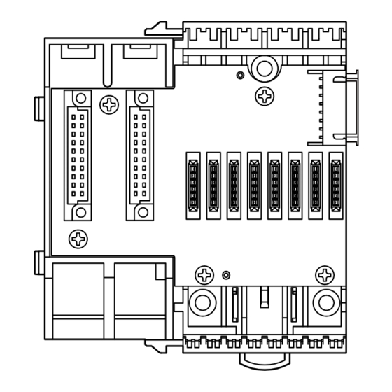
Page 3: Component Identification
TCP connection close time 3 1.0 – 3200.0 (sec.) 180.0 (sec.) TCP connection close time 4 1.0 – 3200.0 (sec.) 180.0 (sec.) Card map 00000000 to FFFFFFFF FFFFFFFF EM-7790 Rev.5 P. 3 / 9 MG CO., LTD. www.mgco.jp 5-2-55 Minamitsumori, Nishinari-ku, Osaka 557-0063 JAPAN... -
Page 4: Terminal Connections
■ EXTERNAL DIMENSIONS unit: mm (inch) LOCKING CLAMP 90 (3.54) 18 (.71) POSITIONING GUIDE ■ CONNECTION DIAGRAM RJ-45 Modbus/TCP INTERNAL BUS CONNECTOR INTERNAL POWER CONFIGURATION JACK JACK EM-7790 Rev.5 P. 4 / 9 MG CO., LTD. www.mgco.jp 5-2-55 Minamitsumori, Nishinari-ku, Osaka 557-0063 JAPAN... - Page 5 R6-NE2 CHECKING ETHERNET CONNECTION ■ IP ADDRESS The R6-NE2 does not support BootP Table Software. The IP Address and Subnet Mask can be configured using the R6CON Configurator Software. The Modbus/TCP Port No. is fixed at 502. ■ DATA ALLOCATION MODE The Data Allocation Mode is usually set to ‘2’...
- Page 6 Contents of the diagnostic data (2 bytes) Change ASCII Input Delimiter Delimiter character of ASCII message Force Listen Only Mode Force the slave into Listen Only Mode EM-7790 Rev.5 P. 6 / 9 MG CO., LTD. www.mgco.jp 5-2-55 Minamitsumori, Nishinari-ku, Osaka 557-0063 JAPAN...
-
Page 7: Modbus I/O Assignments
71, 72 Module address 1 Ao 2 (Float) 189, 190 Module address 31 Ao 1 (Float) 191, 192 Module address 31 Ao 2 (Float) EM-7790 Rev.5 P. 7 / 9 MG CO., LTD. www.mgco.jp 5-2-55 Minamitsumori, Nishinari-ku, Osaka 557-0063 JAPAN... - Page 8 Module address 31 In the Data Allocation Mode 2, the LSB is used for channel 1, and the MSB for channel 2, of an analog module. EM-7790 Rev.5 P. 8 / 9 MG CO., LTD. www.mgco.jp 5-2-55 Minamitsumori, Nishinari-ku, Osaka 557-0063 JAPAN...
- Page 9 Input 1 (Output 1) Input 2 (Output 2) Input 3 (Output 3) Input 4 (Output 4) Not Used (Remains “0”) 0 : OFF 1 : ON EM-7790 Rev.5 P. 9 / 9 MG CO., LTD. www.mgco.jp 5-2-55 Minamitsumori, Nishinari-ku, Osaka 557-0063 JAPAN...
Need help?
Do you have a question about the R6-NE2 and is the answer not in the manual?
Questions and answers