Table of Contents
Advertisement
Quick Links
Safety • Assembly • Operation • Tips & Techniques • Maintenance • Troubleshooting • Parts Lists • Warranty
OPERATOR'S MANUAL
Front Tine Tiller — Model Series 390
IMPORTANT
READ SAFETY RULES AND INSTRUCTIONS CAREFULLY BEFORE OPERATION
Warning: This unit is equipped with an internal combustion engine and should not be used on or near any unimproved forest-covered, brush-
covered or grass-covered land unless the engine's exhaust system is equipped with a spark arrester meeting applicable local or state laws (if any).
If a spark arrester is used, it should be maintained in effective working order by the operator. In the State of California the above is required by law
(Section 4442 of the California Public Resources Code). Other states may have similar laws. Federal laws apply on federal lands. A spark arrester
for the muffler is available through your nearest engine authorized service dealer or contact the service department, P.O. Box 361131 Cleveland,
Ohio 44136-0019.
FORM NO. 769-02926
CUB CADET, P.O. BOX 361131 CLEVELAND, OHIO 44136-0019
10/27/2006
PRINTED IN U.S.A.
Advertisement
Table of Contents

Related Manuals for Cub Cadet Series 390


Summary of Contents for Cub Cadet Series 390
- Page 1 Safety • Assembly • Operation • Tips & Techniques • Maintenance • Troubleshooting • Parts Lists • Warranty OPERATOR’S MANUAL Front Tine Tiller — Model Series 390 IMPORTANT READ SAFETY RULES AND INSTRUCTIONS CAREFULLY BEFORE OPERATION Warning: This unit is equipped with an internal combustion engine and should not be used on or near any unimproved forest-covered, brush- covered or grass-covered land unless the engine’s exhaust system is equipped with a spark arrester meeting applicable local or state laws (if any).
-
Page 2: Table Of Contents
This Operator’s Manual is an important part of your new tiller. It will help you assemble, prepare and maintain the unit for best performance. Please read and understand what it says. Safety Labels ... 3 Safe Operation Practices ... 4 Assembly ... -
Page 3: Safety Labels
Safety Labels Found On Your Tiller Safety Labels WARNING DO NOT remove safety (or any) labels from tiller for any reason. -
Page 4: Safe Operation Practices
Stop the machine if anyone enters the area. • Be careful when tilling in hard ground. The tines may catch in the ground and propel the tiller forward. If this occurs, let go of the handle bars and do not restrain the machine. - Page 5 • The safety labels on the tiller are shown in the “Safety Labels” section. To ensure safe operation of the tiller, follow the instructions on all labels closely.
-
Page 6: Assembly
BEFORE operating your tiller. Figure 3–3: Insert handle into frame. Tiller Setup References to right and left side of tiller are determined from behind the unit in the operating position. Handle Attachment 1. Identify forward clutch cable (A) and reverse clutch cables (B). - Page 7 Figure 3–5. Retain the pin and clip for later reassembly. 2. Remove the two screws from the rear of the tiller frame as shown in Figure 3–6. 3. Insert the depth gage bracket into the frame and reinstall the two screws removed earlier.
-
Page 8: Operating Your Tiller
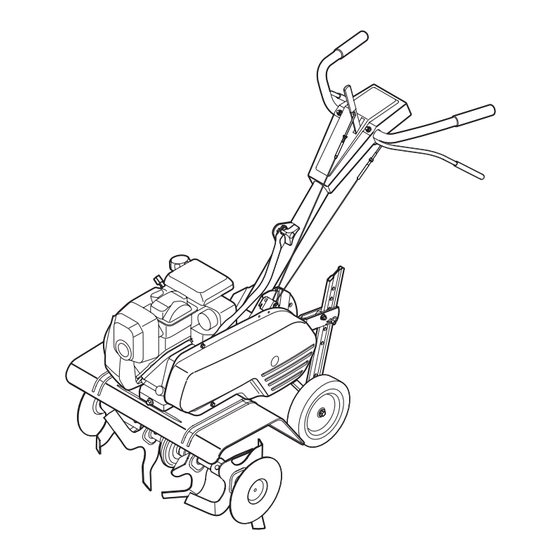
Depth Stake The depth stake controls the tilling depth. Refert to Operating Your Tiller later in this section for further instructions on its use. Your Tiller Throttle Control Tiller Tines Figure 4–1: The major parts of the tiller... -
Page 9: Operating Your Tiller
Before Starting Gas And Oil Fill-Up Service the engine with gasoline and oil as instructed in the separate engine manual packed with your tiller. Read instructions carefully. WARNING: Use extreme care when handling gasoline. Gasoline is extremely flammable and the vapors are explosive. -
Page 10: Depth Stake
Your tiller is designed for seed bed preparation, cultivat- ing, furrowing, and mulching. Wheel Position The tiller is shipped with the wheels adjusted so that the unit sits level. The wheels need to be adjusted to meet your tilling needs before operation. This adjustment is made by removing the clevis pin from the wheel yoke and raising the wheels to the desired height. -
Page 11: Tilling Procedure
The tiller has many uses other than tilling and cultivating a garden. One of these is the preparation of lawn area for seeding. The tiller will prepare a deep seed bed which will be free of hard untilled spots, allowing a better stand of grass to grow. -
Page 12: Maintaining Your Tiller
Order all belts through you authorized service dealer. 1. Disconnect and ground the spark plug wire against the engine. 2. Remove the belt cover from the left side of the tiller by removing the two self-tapping screws and hex stop nut and washer. - Page 13 Do not push down on handles so that wheels are lifted off the ground while using the tine drive, or tiller could move backward and cause personal injury. Never attempt to make any adjustments while engine is...
-
Page 14: Cable Adjustment
Reverse Tine Engagement Cable Maintaining Your Tiller Figure 5–7: Reverse drive belt removal. WARNING Disconnect the spark plug wire and ground it against the engine before performing any repairs or maintenance. Figure 5–8: Reverse drive belt removal. Figure 5–9: Reverse drive belt removal. -
Page 15: Off-Season Storage
Off-Season Storage If the tiller will not be used for a period longer than 30 days, the following steps should be taken to prepare the tiller for storage. 1. Clean the exterior of engine and the entire tiller thoroughly. Lubricate the tiller as described in the lubrication instructions. -
Page 17: Illustrated Parts List
Carr. Bolt 5/16-18 x 1 736-0242 Bell. Wash.34” I.D. 720-0195 Hand Knob 750-0470 Spacer Illustrated Parts List Model 390 Series To order replacement parts, contact your local Cub Cadet dealer; or call our dealer locator number at 1 (877) 282-8684; or log onto www.cubcadet.com... - Page 18 †††Honda Engine...
- Page 19 Screw 5/16-18 x 1.50 712-3010 Hex Nut 5/16-18 736-0242 Bell Washer Illustrated Parts List Model 390 Series To order replacement parts, contact your local Cub Cadet dealer; or call our dealer locator number at 1 (877) 282-8684; or log onto www.cubcadet.com...
-
Page 20: Warranty
MANUFACTURER’S LIMITED WARRANTY FOR The limited warranty set forth below is given by Cub Cadet LLC with respect to new merchandise purchased and used in the United States, its possessions and territories. “Cub Cadet” warrants this product against defects in material and...
Need help?
Do you have a question about the Series 390 and is the answer not in the manual?
Questions and answers