Sign In
Upload
Download
Table of Contents
Contents
Add to my manuals
Delete from my manuals
Share
URL of this page:
HTML Link:
Bookmark this page
Add
Manual will be automatically added to "My Manuals"
Print this page
×
Bookmark added
×
Added to my manuals
Manuals
Brands
Schmalz Manuals
Control Unit
LQEi
Operating instructions manual
Schmalz LQEi Operating Instructions Manual
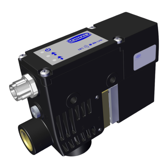
Compact valve
Hide thumbs
1
2
Table Of Contents
3
4
5
6
7
8
9
10
11
12
13
14
15
16
17
18
19
20
21
22
23
24
25
26
27
28
29
30
31
32
33
34
35
36
37
38
39
40
41
42
43
44
45
46
page
of
46
Go
/
46
Contents
Table of Contents
Bookmarks
Table of Contents
Table of Contents
1 Important Information
Note on Using this Document
The Technical Documentation Is Part of the Product
Type Plate
Symbols
2 Fundamental Safety Instructions
Intended Use
Non-Intended Use
Personnel Qualifications
Warnings in this Document
Residual Risks
Modifications to the Product
3 Product Description
Applying Suction to the Workpiece/Part
Dropping off the Workpiece/Part
Operating Modes
Product Name
Product Design
Description of Indicator Elements
Interface NFC
4 Technical Data
Parameters
Electrical Parameters
Flow Capacity
Dimensions
Pneumatic Circuit Plans
Factory Setting
5 Functional Description
Signal Type
System Commands
User-Specific Localization
Device Data
Process Data Monitoring
Device Status
Displaying Errors
Access Control
Switch-On and Switch-Off Delay
Set Permissible Evacuation Time T1 (0X006B)
Setting the Function of Input PD1.0
Counters
Timing
IO-Link Events
Condition Monitoring Events and Status Indicator
Switching Points
6 Checking the Delivery
7 Installation
Installation Instructions
Mechanical Attachment
Pneumatic Connection
Electrical Connection
8 Operation
General Preparations
9 Warranty
10 Maintenance and Cleaning
Safety Instructions for Maintenance
Cleaning the Device
Cleaning the Screen
Replacing the Press-In Screen in the Vacuum Connection for the Gripper
11 Taking the Product out of Operation and Disposal
12 Spare Parts
13 Accessories
14 Attachment
Lqei_Datadictionary.pdf
EU Declaration of Conformity
Advertisement
Quick Links
Download this manual
Operating instructions
Compact Valve LQEi,c
WWW.SCHMALZ.COM
EN-US · 30.30.01.03650 · 00 · 09/23
Table of
Contents
Previous
Page
Next
Page
1
2
3
4
5
Advertisement
Table of Contents
Need help?
Do you have a question about the LQEi and is the answer not in the manual?
Ask a question
Questions and answers
Related Manuals for Schmalz LQEi
Control Unit Schmalz LQEc 8 24V-DC 3/2 IMP PNP Operating Instructions Manual
Compact valve (46 pages)
Control Unit Schmalz SCPi Brief Operating Instructions
(68 pages)
Control Unit Schmalz SCPMi Operating Instructions Manual
Mini compact valve (16 pages)
Control Unit schmalz SVK Series Operating Instructions
Check valves svk, svkg, svv (2 pages)
Control Unit Schmalz 10.08.09.00014 Operating Instructions Manual
Smart communication module (scm) (32 pages)
Control Unit schmalz 10.02.02.02795 Operating Instructions Manual
Six-circuit ejector block (28 pages)
Control Unit Schmalz MATCH ABB IRB 1100 Operating Instructions Manual
Quick-change module rmqc (24 pages)
Control Unit Schmalz Ecosystem MATCH Operating Instructions Manual
Ejector module recbi / end-of-arm (84 pages)
Control Unit Schmalz EMVP 10 Operating Instructions Manual
Solenoid valves (8 pages)
This manual is also suitable for:
Lqec
Lqec 8 24v-dc 3/2 imp pnp
10.05.11.00008
Lqei,c
Table of Contents
Print
Rename the bookmark
Delete bookmark?
Delete from my manuals?
Login
Sign In
OR
Sign in with Facebook
Sign in with Google
Upload manual
Upload from disk
Upload from URL


Need help?
Do you have a question about the LQEi and is the answer not in the manual?
Questions and answers