
Related Manuals for Schmalz MATCH ABB IRB 1100


Summary of Contents for Schmalz MATCH ABB IRB 1100
- Page 1 Operating instructions Quick-Change Module RMQC | End-of- Arm Ecosystem MATCH ABB IRB 1100 WWW.SCHMALZ.COM EN-US · 30.30.01.03064 · 01 · 12/22...
- Page 2 Any modifications to or abridgments of the document are prohibited without explicit writ- ten agreement from J. Schmalz GmbH. J. Schmalz GmbH · Johannes-Schmalz-Str. 1 · 72293 Glatten, Germany · T: +49 7443 2403-0 schmalz@schmalz.de 2 / 24...
-
Page 3: Table Of Contents
Contents Contents 1 Important Information ........................... 4 Note on Using this Document...................... 4 The technical documentation is part of the product ................ 4 Type Plate............................. 4 Symbols.............................. 5 2 Fundamental Safety Instructions........................ 6 Intended Use ............................ 6 Non-Intended Use.......................... 6 Personnel Qualifications........................ -
Page 4: Important Information
ð Failure to follow the instructions in these Operating instructions may result in injuries! ð Schmalz is not liable for damage or malfunctions that result from failure to heed these instructions. If you still have questions after reading the technical documentation, contact Schmalz Service at: www.schmalz.com/services... -
Page 5: Symbols
1 Important Information 1.4 Symbols This symbol indicates useful and important information. ü This symbol represents a prerequisite that must be met prior to an operational step. 4 This symbol represents an action to be performed. ð This symbol represents the result of an action. Actions that consist of more than one step are numbered: 1. -
Page 6: Fundamental Safety Instructions
2.2 Non-Intended Use Schmalz does not accept any liability for any direct or indirect losses or damages that result from using the product. This applies, in particular, to any use of the product that is not in accordance with the in- tended purpose and to any use that is not described or mentioned in this documentation. -
Page 7: Product Description
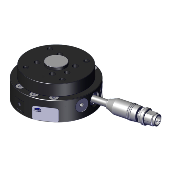
3 Product description 3 Product description 3.1 Product Variants Schmalz part no. Zimmer Group part no. Model 10.08.09.00021 LWR50F-15-01-A Digital I/O IRB 1100 10.08.09.00022 LWR50F-15-04-A IO-Link IRB 1100 10.08.09.00023 LWR50F-15-05-A IO-Link LED-B IRB 1100 3.2 Product Design Energy supply of robot/fixed member Pneumatics connector (optional) -
Page 8: Description Of Functions
The colors of the LED ring (1) provide information about the status of the IO-Link devices in the loose member. The LED ring (1) provides a 360° status display. LED color Behavior SCHMALZ IO-Link product Zimmer IO-Link product sta- status —... -
Page 9: Connect Led
3 Product description 3.5 Connect LED The colors of the Connect LED (1) provide infor- mation about the status of the power supply and coupling. LED color Behavior Status — None — No power supply Continu- Loose member not coupled ous light Green Continu- Loose member coupled... -
Page 10: Technical Data
4 Technical Data 4 Technical Data 4.1 Tool-Changer-Specific Data Electrical energy transmission Integrated Interlocking hub 1 mm Repeatability in X, Y 0.05 mm Repeatability in Z 0.05 mm Tightening force 50 N Releasing force 0 N Max. axis offset during coupling in X, Y 1.0 mm 4.2 Technical Data 10.08.09.00021 10.08.09.00022 10.08.09.00023... -
Page 11: Dimensions
4 Technical Data 4.4 Dimensions Parameter mapping valid for 10.08.09.00021 and 10.08.09.00022 Parameter mapping valid for 10.08.09.00023 M7 internal M3 internal M4 internal 31.5 thread thread thread Part no. 10.08.09.00021 M12-AG 10.08.09.00022 10.08.09.00023 All dimensions given in millimeters [mm]. EN-US · 30.30.01.03064 · 01 · 12/22 11 / 24... -
Page 12: Transportation And Storage
1. Compare the entire delivery with the supplied delivery notes to make sure nothing is missing. 2. Damage caused by defective packaging or occurring in transit must be reported immediately to the carrier and J. Schmalz GmbH. 5.2 Unpacking the Device Remove product packaging only to the extent required for further internal transport. -
Page 13: Installation
Refer to the specifications provided by the relevant robot manufacturer for the tightening torque of the mounting bolts. Schmalz also recommends verifying the permissible load capacity of the re- quired screw connections in accordance with VDI 2230. In high ambient temperatures, the product must be mounted on heat-dissipating materials. The service life of the product may be reduced if it is continuously operated under very high ambient temperatures and with rapid clock cycles. -
Page 14: Mounting Of The Variant With An Intermediate Flange
6 Installation 6.2 Mounting of the Variant with an Intermediate Flange The displayed figures are only examples. Depending on the particular design, they can differ from the product. Follow the work steps below during mounting: ü The customer supplies the required number and type of mounting bolts. 1. -
Page 15: Installing The Energy Supply
6 Installation 5. Position the flange (2) in the correct position on the intermediate flange (1) and loosely at- tach the mounting bolts that were removed in the first step. 6. Fasten the mounting bolts cross-wise with the tightening torque specified in VDI 2230. 6.3 Installing the Energy Supply The product is designed only for electrical operation with a 24V DC supply voltage. -
Page 16: Static Electricity
6 Installation 6.3.2 RMQC part no. 10.08.09.00022 and 10.08.09.00023 PIN assignment Name Cable pin Cable color 12-pin plug S24V Brown P24V Blue SGND White PGND Gray IO-Link Green 6.4 Static Electricity NOTE Static Electricity Failure to comply may result in damage to property 4 If ESD-sensitive parts come into contact with the product, you must ensure that the product is grounded. -
Page 17: Manual Robot Soft-Switch (Option)
7 Manual Robot Soft-Switch (Option) 7 Manual Robot Soft-Switch (Option) The manual soft-switch is available only in DIO mode if the relevant robot supports this function (apart from during execution with IO-Link). The product is equipped with a “freedrive” button (1) for manual robot soft-switches. You must follow the steps below to manually teach in the robot position: 1. -
Page 18: Maintenance And Cleaning
8 Maintenance and Cleaning 8 Maintenance and Cleaning 8.1 Safety Instructions for Maintenance WARNING Risk of injury due to incorrect maintenance or troubleshooting 4 Check the proper functioning of the product, especially the safety features, after every maintenance or troubleshooting operation. CAUTION Blowing off or cleaning the product with compressed air Risk of injury and damage to the product 4 Never blow off the product with compressed air. -
Page 19: Maintenance
Unauthorized disassembly and assembly of the product can lead to complications, as special assembly de- vices are sometimes required. Schmalz stipulates the following checks and check intervals. The operator must comply with the legal regulations and safety regulations applicable at the location of use. These intervals apply to single-shift operation. -
Page 20: Accessories
The function of the product cannot be guaranteed if you use accessories that are not sold or authorized by Schmalz or the Zimmer Group. Schmalz accessories are tailored especially to the individual products. You can find optional accessories and the accessories included in delivery at www.schmalz.com. -
Page 21: Taking The Product Out Of Operation And Disposal
10 Taking the Product Out of Operation and Disposal 10 Taking the Product Out of Operation and Disposal If the product reaches the end of the utilization phase, it may be fully disassembled and disposed of. Only qualified specialist staff may prepare the product for disposal. 1. -
Page 22: Declarations Of Conformity
11 Declarations of Conformity 11.1 EC Conformity EU Declaration of Conformity The manufacturer Schmalz confirms that the product with the name “ejector module RECB MATCH” that is described in these operating instructions complies with the following applicable EC directives: 2011/65/EU RoHS Directive... -
Page 23: Ukca Conformity
11 Declarations of Conformity 11.2 UKCA Conformity The manufacturer Schmalz confirms that the product described in these operating instructions fulfills the following applicable UK regulations: 2012 The Restriction of the Use of Certain Hazardous Substances in Electrical and Electronic Equipment Regulations... - Page 24 At Your Service Worldwide Vacuum automation Handling systems WWW.SCHMALZ.COM/AUTOMATION WWW.SCHMALZ.COM/EN-US/VACUUM-LIFTERS- AND-CRANE-SYSTEMS J. Schmalz GmbH Johannes-Schmalz-Str. 1 72293 Glatten, Germany T: +49 (0) 7443 2403-0 schmalz@schmalz.de WWW.SCHMALZ.COM...
Need help?
Do you have a question about the MATCH ABB IRB 1100 and is the answer not in the manual?
Questions and answers