
Subscribe to Our Youtube Channel
Related Manuals for Schmalz 10.02.02.02795


Summary of Contents for Schmalz 10.02.02.02795
- Page 1 Innovative Vacuum for Automation Six-Circuit Ejector Block 10.02.02.02795 / 10.02.02.03284 Operating Instructions...
- Page 2 Six-Circuit Ejector Block Operating Instructions C H MA LZ...
-
Page 3: Table Of Contents
Six-Circuit Ejector Block Operating Instructions ONTENTS Safety Information ................1-4 Important symbols ....................1-4 General safety information ..................1-5 Intended use ......................1-5 Description..................2-6 Description....................... 2-6 Mechanical function description ................2-7 Electronic function description ................. 2-7 Process flow diagram ....................2-8 Display elements ..................... -
Page 4: Safety Information
Six-Circuit Ejector Block Operating Instructions AFETY NFORMATION MPORTANT SYMBOLS Identifies a direct risk of danger. If it is not avoided, death and serious injuries may result. Danger Danger Identifies a potentially dangerous situation. If it is not avoided, slight or minor injuries may result. Caution Caution C H MA LZ... -
Page 5: General Safety Information
Six-Circuit Ejector Block Operating Instructions ENERAL SAFETY INFORMATION These operating instructions contain important information on using the ejector system. Please read the operating instructions thoroughly and keep them for later reference. Compressed air could cause closed containers to explode. A vacuum could cause closed containers to implode. -
Page 6: Description
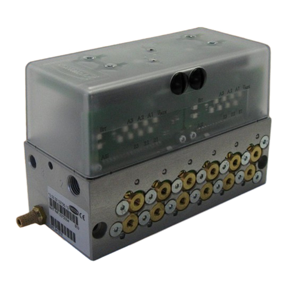
Six-Circuit Ejector Block Operating Instructions ESCRIPTION ESCRIPTION Item Description Attachment holes Ø 6.6 mm, on both sides Main compressed air connection, 1/4" connection thread, on both sides Alternate compressed air connection for external actuators, 1/8" connection thread, on both sides Central deaeration hole, on both sides Silencer exhaust, on both sides Auxiliary voltage connection AUX (black dual-conductor flat cable) -
Page 7: Mechanical Function Description
Six-Circuit Ejector Block Operating Instructions ECHANICAL FUNCTION DESCRIPTION The ejector block consists of six working circuits, which can be controlled independently of one another. By applying the main compressed air [2] and controlling the appropriate working circuit using the ASi bus, the main compressed air is routed through at the vacuum connections [12] and the ejector blows for as long as the signal is present. -
Page 8: Process Flow Diagram
Six-Circuit Ejector Block Operating Instructions ROCESS FLOW DIAGRAM C H MA LZ... -
Page 9: Display Elements
Six-Circuit Ejector Block Operating Instructions ISPLAY ELEMENTS LEDs [10] that display the status of the ASi slaves are located on the front of the ejector block. The LED assignment is laid out on the printed-circuit board and on the cover. For each ASi slave, there are LEDs for ASi voltage, ASi communication, the auxiliary power supply, the inputs and the outputs. -
Page 10: Display Element Functions
Six-Circuit Ejector Block Operating Instructions ISPLAY ELEMENT FUNCTIONS Colour State Function ASi voltage ok Green No ASi voltage Communication ok Fault Communication fault or address = 0 Flashing Overload at one or more outputs Auxiliary power supply ok Green No voltage at the auxiliary power supply Output 1 activated (only when auxiliary power supply ok) Yellow Output 1 deactivated... -
Page 11: Initial Startup
Six-Circuit Ejector Block Operating Instructions NITIAL TARTUP NSTALLATION AND OPERATION For safe installation and smooth operation, please observe and maintain the following: Carefully remove the components from the packaging. Protect the components from being damaged. During installation and maintenance, make sure that the device is de-energized and depressurised and that it may not restart without authorisation. -
Page 12: Mounting
Six-Circuit Ejector Block Operating Instructions OUNTING Read the safety instructions before beginning the mounting procedure. Caution Caution ECHANICAL ATTACHMENT Choose an installation position. Leave sufficient space to easily change the nozzles when required. Attach the ejector using the Ø 6.6 mm through-holes [1]. ... -
Page 13: Electrical Connection
Six-Circuit Ejector Block Operating Instructions ECOMMENDED LINE CROSS SECTIONS INTERNAL DIAMETERS On the vacuum side, the internal diameter should be at least 4 mm per nozzle. For a hose longer than 2 m, use the next largest line cross section. PERATING MEDIUM Filtered air or neutral gas, 50 µm, oiled or un-oiled, in accordance with EN 983. -
Page 14: Maintenance
Six-Circuit Ejector Block Operating Instructions AINTENANCE ENERAL MAINTENANCE Remove dirt from outside of device by cleaning with a soft cloth and soap suds (max. 60 °C). Ensure that the silencer and the controller are not soaked with soap suds. Sealed components (sealing paint) must not be unfastened or removed. Caution Caution ILENCER MAINTENANCE... - Page 15 Six-Circuit Ejector Block Operating Instructions ACUUM KIT MAINTENANCE The six vacuum kits [9] can be completely replaced. In order to do this, remove the attachment screws [13] from the vacuum kit. Each vacuum kit is affixed using two attachment screws. ...
-
Page 16: Troubleshooting
Six-Circuit Ejector Block Operating Instructions ROUBLESHOOTING Fault Possible cause Recommended action Vacuum level is Silencer is soiled Replace silencer not reach or Leakage in hose line Check hose connections vacuum is created Leakage at suction pad Check suction pad too slowly Operating pressure too low Increase operating pressure (observe max. -
Page 17: Electrical Data
Six-Circuit Ejector Block Operating Instructions ECHNICAL PECIFICATIONS LECTRICAL DATA Operating the ejector system outside of the specified values can result in damage to the system and attached components. Caution Caution The system may only be run via power supply units with protected extra-low voltage (PELV) and safe electrical cut-off of the operating voltage, in accordance with EN 60204. -
Page 18: Mechanical Data
Six-Circuit Ejector Block Operating Instructions ECHANICAL DATA ECHANICAL PARAMETERS Characteristic Unit Value Protection class IP 65 Ambient temperature °C 0 to +50 Medium temperature °C 0 to +50 (medium to be evacuated) Storage temperature °C -25 to +70 Main compressed air operating 4.5 to 6 pressure Main compressed air rated... -
Page 19: Dimensions
Six-Circuit Ejector Block Operating Instructions IMENSIONS C H MA LZ 6-19... -
Page 20: Pneumatic Circuit Plan
Six-Circuit Ejector Block Operating Instructions NEUMATIC CIRCUIT PLAN a: Idle position b: Work position 6-20 C H MA LZ... -
Page 21: Vacuum Switch (Optional)
Six-Circuit Ejector Block Operating Instructions ACUUM WITCH PTIONAL Each working circuit of the ejector block can be fitted with an optional vacuum switch. Before the modification, the ejector block must be disconnected from the electrical and compressed air supply. Caution Caution Note: In the version with external inputs, connections X7, X8, X9 and X12 are already... - Page 22 Six-Circuit Ejector Block Operating Instructions 3. Structure of vacuum switch The vacuum switch is set up as a kit. It includes the switch itself [15], an extension [16] and two gaskets [17]. The extension is only used if the switches are installed next to one another.
-
Page 23: Ejector With External Inputs (10.02.02.03284)
Six-Circuit Ejector Block Operating Instructions JECTOR WITH XTERNAL NPUTS (10.02.02.03284) Ejector 10.02.02.03284 is a modified version of ejector 10.02.02.02795. The differences in the features are described in this chapter. All other characteristics remain applicable. ESCRIPTION Item Description M8 connector - external sensor “IN1”... -
Page 24: Plug Assignment For External Sensors
Six-Circuit Ejector Block Operating Instructions LUG ASSIGNMENT FOR EXTERNAL SENSORS “IN1” “IN2” The assignments for the M8 connectors [18] and [19] are as follows: Plugs Assignment ASi operating voltage ASi ground Input “IN1” / “IN2” SSIGNMENT OF THE INPUTS The modification to the ejector results in a pre-assignment of the ASI inputs. If additional vacuum sensors are added, these inputs can no longer be used. -
Page 25: Warranty, Spare And Wearing Parts
Six-Circuit Ejector Block Operating Instructions ARRANTY PARE AND EARING ARTS This system is guaranteed in accordance with our general terms of trade and delivery. This also applies to spare parts, provided they are original parts supplied by us. We accept no liability for damage caused by the use of spare parts or accessories made by other manufacturers. - Page 26 Six-Circuit Ejector Block Operating Instructions 9-26 C H MA LZ...
- Page 27 We reserve the right to make technical changes. No responsibility is taken for printing or other types of errors. All information and specifications may be changed without advanced notice. © J. Schmalz GmbH. All rights reserved. 30.30.01.00426 Status 06.2013 / Index 00...
Need help?
Do you have a question about the 10.02.02.02795 and is the answer not in the manual?
Questions and answers