Advertisement
Quick Links
Advertisement

Related Manuals for maxwatt MX3000iS


Summary of Contents for maxwatt MX3000iS
- Page 1 INVERTER GENERATOR OPERATOR’S MANUAL...
-
Page 4: Table Of Contents
TABLE OF CONTENTS Introduc on ..............Safety Informa on ............Generator Safety Warnings..........Know Your Generator ............. Generator Prepara on ........... Star ng the Generator ........... Shu ng O the Generator ..........Maintenance ..............Transporta on & Storage ..........Troubleshoo ng Guide ..........Wiring Diagram .............. - Page 5 MAXWATT is constantly improving its products. All informa on supplied in this manual is based on the latest product informa on available at the me of prin ng. The speci ca ons outlined herein are subject to change without no ce or obliga on.
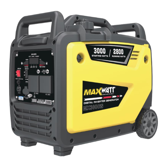
- Page 6 SPECIFICATIONS Model NO. MX3000iS Star ng Wa age 3000W Running Wa age 2800W Phase Single Frequency 50Hz Voltage AC 240V Amperage 11.7A 4-stroke, OHV, single cylinder with forced air- Engine Type cooling system Engine 139cc Displacement Fuel Tank Capacity 6.0L, 87 octanes minimum Oil Capacity 0.45 L...
- Page 7 For any queries on the above, please contact , the o cial service agent for all MAXWATT generators a water pumps. The range of MAXWATT generators is safe a reliable, but incorrect usage of these pro cts may cause personal injury a amage to the machine.
- Page 8 GENERAL WARNINGS & DISCLAIMER READ and UNDERSTAND this manual completely before using the engine. Failure to properly set up, operate and maintain this engine could result in serious injury or death from carbon monoxide poisoning, electric shock, e/explosions and/or burns. In par cular be aware of the following hazards: CD Poisoning Engines give...
- Page 9 STOP! CHOOSE THE RIGHT GENERATOR FOR YOUR NEEDS. See the Power Load Planning and Management sec on to determine your power load requirements and then compare to the generator’s rate capacity. INSPECT COMPONENTS Closely inspect to make sure that there are not any components missing or damaged. ARRANGE FOR PROFESSIONAL INSTALLATION of a transfer switch if you will be connec ng the generator to your building’s system.
- Page 10 4. DO NOT overreach. Keep proper foo ng and balance at all mes. This enables r control of the generator in unexpected situa ons. 5. Dress properly. DO NOT wear loose clothing, gloves, neck es or jewellery. Keep your hair and clothing away from moving parts. Loose clothes, jewellery or long hair can be caught in moving parts.
- Page 11 during opera on. A re or an explosion could result. 11. Always turn o the generator and remove the spark plug(s) or spark plug wire(s) before working on the generator to prevent accidental star ng. Always discharge the capacitor before working on the generator head to prevent electrical shock.
- Page 12 Never smoke near the running engine and never operate near sources of sparks or ames. SERVICE Have your generator serviced by a quali ed repair person using only factory approved replacement parts. This will ensure that the safety of the generator is maintained. Incorrectly d parts will void your warranty.
- Page 13 TYPICAL SOURCES OF STATIC ELECTRIC HAZARDS DURING FUELLING The following objects can accumulate a sta c electric charge and cause an igni on spark in typical fuelling situa ons: 1. Ungrounded tanks/containers. Any ungrounded fuel tank or container can accumulate a sta c electric charge as a result of contact with other objects or fric on during transporta on.
- Page 14 Note: You must NOT overload the generator. Overloading may cause serious damage to the generator and a ached electrical devices. SET UP AS BUILDING BACK UP To set up as a building backup, you must arrange for a licensed electrician to connect the generator to your building’s electrical system via the installa on of an approved transfer switch.
- Page 15 GROUNDING THE GENERATOR 1. Standard generators are protected by electrical separators. This equipment has a thermic protec on device and/or magnet-to-thermic device to protect against a surge of current, overloading and short-circui ng. In these cases, the generator should under NO circumstances, be earthed using the terminal “PE”...
- Page 16 EXTENSION CORDS Extension cords may be used to power devices that are located at a distance from the generator. However, use only Australian approved outdoor-rated, grounded extension cords. Locate the generator in a convenient place and where possible, avoid long extension leads and possible damage to leads by pedestrian or vehicular tra c.
- Page 17 basements, sheds or boxes. These spaces can trap poisonous gases, even if you run a fan or open windows. 3. Ensure that working, ba ry-operated or ba ery back-up carbon monoxide alarms are used in any dwelling/structure that is in close proximity to the running operator. Note: This generator is NOT designed or approved for use in vehicles or marine applica ons.
- Page 18 Keep a e ex nguisher rated “ABC” nearby. Keep it properly charged and be familiar with its use. NO WET CONDITIONS Choose a loca on where the generator will NOT be exposed to rain, snow or direct sunlight. Exposure to water can cause an electric shock. You may operate the generator under an outdoor canopy-like structure of heat-resistant material that is open on all sides.
-
Page 19: Safety Informa On
SAFETY INFORMATION WARNING: Before opera ng the generator, make sure to read all safety warnings and all instruc- ons. Failure to follow the warnings and instruc ons may result in electric shock, e or serious injury. SAFETY INTRODUCTION Safety is a combina on of common sense, staying alert, and knowing how your tool works. This manual contains important informa on regarding the generator’s poten al safety concerns, as well as prepara on, opera on, and maintenance instruc ons. -
Page 20: Generator Safety Warnings
GENERATOR SAFETY WARNINGS DANGER: CARBON MONOXIDE Using a generator indoors CAN KILL YOU IN MINUTES. A generator exhaust contains carbon monoxide (CO). This is a poison gas you cannot see or smell. If you can smell the generator exhaust, you are breathing CO. - Page 21 GENERATOR SAFETY WARNINGS WARNING: Do not let comfort or familiarity with the product replace strict adherence to product safety rules. Failure to follow the safety instruc ons may result in serious personal injury. OPERATING ENVIRONMENT 1. Using a generator indoors can kill you in minutes. Only use a generator OUTSIDE and far away from windows, doors and vents.
- Page 22 6. Never modify the generator in any way. Modifying or using the machine for any other purpose for which it is not designed may result in serious injuries, machine damage and voiding of the warranty...
- Page 23 GENERATOR SAFETY WARNINGS GENERATOR OPERATION 1. Only use the generator for its intended purposes. Modifying or using the generator for opera ons for which it was not designed may cause hazards and personal injury. 2. Do not touch bare wires or receptacles (outlets). 3.
-
Page 24: Know Your Generator
KNOW YOUR GENERATOR GENERATOR Carrying Handle Carrying Handle Fuel Cap Telescopic Rod Control Panel Maintenance Cover Wheel Foot Recoil Starter Muffler Multi-switch START - RUN - STOP Maintenance Cover... - Page 25 CONTROL PANEL MAIN SW. LOW IDLE CIRCUIT BUDAI PROTECTOR BUDAI CIRCUIT PROTECTOR AC 240V AC 240V DC 12V PARALLEL OPERATION OUTLETS 1.Main Sw. 7.AC Receptacles 2.Low Idle 8.Grounding Nut 3.Output Indicator 4.Overload Alarm 10.DC 5V USB Outlets 5.Low Oil Alarm 11.DC 12V 6.Circuit Protector 12.Circuit Protector...
- Page 26 PARALLEL OPERATION The parallel opera on outlets (Fig. 2) allows you to connect two of our generators to increase the total available electrical power.The load plugs can now be plugged into the AC sockets. Ensure that the load is split between the 2 sockets, DO NOT OVERLOAD THE SOCKET WITH MORE THAN 15 Fig 2 AMPS OR 3600W.
- Page 27 be es mated by adding only the item(s) with the highest addi onal star ng (max.) to the total rated wa s. Example: Tool or Running Addi onal Appliance Wa s* Star ng Wa s* Refrigerator 1350 Portable Fan Laptop 46 in.
- Page 28 NOTICE: Do not overload the generator’s capacity. Exceeding the generator’s wa age/amperage capacity may damage the generator and/or electrical devices connected to it.
- Page 29 The chart below serves as a reference for the es mated wa age requirements of common electrical de-vices. However, do not solely rely on this chart - all electronics and appliances are built di erently. Always check the wa age listed on the electrical device before consul ng this chart.
-
Page 30: Generator Prepara On
GENERATOR PREPARATION The following sec on describes the necessary steps to prepare the generator for use. Failure to perform these steps properly can damage the generator or shorten its life. STEP 1 - ADD/CHECK OIL The generator is shipped without oil. User must add the proper amount of oil before opera ng the generator for the rst me. - Page 31 For subsequent opera on, the oil level should be checked before each use, or a r every 8 hours of opera on. The generator is equipped with a low-oil sensor and will NOT start without a su cient amount of oil. To check oil level (before every subsequent start): 1.Place the generator on a level surface.
- Page 32 NOTICE: Never use an oil/petrol mixture. Never use old petrol. Keep petrol away from sparks, open ames, pilot lights, heat and other sources of igni on. Avoid ge ng dirt or water into the fuel tank. Petrol can age in the tank and make star ng di cult. Never store generator for more than 2 months with fuel in the tank.
- Page 33 GROUND THE GENERATOR To reduce the risk of electric shock and to maximize safety, the generator should be properly grounded. Ground the generator by ghtening the grounding nut on the front control panel (Fig. 11) against a grounding wire. A generally acceptable grounding wire is a No. 12 AWG (American Wire Gauge) stranded copper wire.
- Page 34 STARTING THE GENERATOR Before star ng the generator, make sure you have read and performed the steps in the “Generator Prepara on” sec on of this manual. If you are unsure about how to perform any of the steps in this manual, please contact your authorized service centre. DANGER: CARBON MONOXIDE Using a generator indoors CAN KILL YOU IN MINUTES.
- Page 35 WARNING: The generator should ONLY be connected to electrical devices, either directly or with an extension cord. NEVER CONNECT TO A BUILDING ELECTRICAL SYSTEM without a quali ed electrician and connected to a transfer switch as a separately derived system. Such connec ons must comply with local electrical laws and codes. Failure to comply can create a back-feed, which may result in serious injury or death to u ty workers.
-
Page 36: Star Ng The Generator
Before star ng the generator: 1.Verify that the generator is outside on a dry, level surface. Allow at least two feet of clearance on all sides of the generator. 2.To maximize safety, check that the generator is properly grounded (see “GROUND THE GENERATOR”). - Page 37 SHUTTING OFF THE GENERATOR CAUTION: Unplugging running devices can cause damage to the generator. Never stop the engine with electrical devices connected and running. MAIN SW. 1. Turn off all electrical devices prior to unplugging them from the generator. Unplugging running devices can cause damage to the generator.
-
Page 38: Maintenance
MAINTENANCE RECOMMENDED MAINTENANCE SCHEDULE Proper rou ne maintenance of the generator will help prolong the life of the machine. Please perform maintenance checks and opera ons according to the Maintenance Schedule. If there are any ques ons about the maintenance procedures listed in this manual, please contact your authorized service center. WARNING: Never perform maintenance opera ons while the generator is running. - Page 39 *Clean/change more o n under dusty condi ons or opera ng under heavy load. IMPORTANT GENERATOR MAINTENANCE TIPS: • Drain your carburetor a er each use and before storage to prevent it from clogging. • Do not store the generator with fuel inside the tank for more than 2 months - the fuel will go bad. •...
- Page 40 SPARK PLUG MAINTENANCE Refer to Recommended Maintenance Schedule for maintaining the spark plug. The spark plug must be properly gapped and free of deposits in order to ensure proper engine opera on. If the engine is hot, allow it to cool before servicing the spark plug. To inspect or replace the spark plug: 1.
- Page 41 SPARK ARRESTOR MAINTENANCE Inspect and clean the spark arrestor every 100 hours of opera on. The spark arrester is located outside the mu er, which gets very hot during opera on. Allow the engine to cool completely before servicing the spark arrester. To inspect and clean the spark arrester: 1.
- Page 42 5. Prepare an approved petrol -storage container and direct the end of the drain tube into the container. 6. Open up the carburetor drain screw (Fig. 24) with a at-head screwdriver (not included) and drain out any petrol that has built up inside the carburetor through the drain tube into the approved petrol -storage container.
- Page 43 7. Reinstall the black rubber seal. Oil drain NOTE: Never dispose of used engine oil in the trash or plug down a drain. Please call a local recycling centre or auto Oil hole garage to arrange proper oil disposal. 8. With the generator in a level posi on and Black rubber with engine oil following the instruc ons seal (bo om)
- Page 44 TRANSPORTATION & STORAGE TRANSPORTING THE GENERATOR To prevent fuel spillage when transpor ng, be sure to perform the following: 1.Tighten the fuel cap and turn the vacuum relief valve to “OFF”. 2. Set the engine switch to “OFF”. 3. Drain the fuel tank if possible. 4.
- Page 45 PRODUCT DISPOSAL Do not dispose of used generator or parts with your household waste. This product contains electrical or electronic components that should be recycled. Please take this product to your local recycling facility for responsible disposal to minimize its environmental impact. Do not dispose of used oil or fuel in the trash or down a drain.
- Page 46 TROUBLESHOOTING GUIDE ENGINE WILL NOT START Possible Cause Solu on Engine switch is in the OFF posi on. Turn engine switch to the ON posi on. No fuel. Fill fuel tank. Stale petrol or water in petrol. Drain en e system and re ll with fresh fuel. Engine oil level is low.
- Page 47 AC RECEPTACLE DOES NOT WORK. Possible Cause Solu on OUTPUT indicator is OFF, and Check AC load. Stop and restart the engine. Check OVERLOAD indicator is ON. the cooling air inlet. Stop and restart the engine. AC Circuit protector(s) tripped. Check AC load and reset AC circuit protector(s) GFCI system ac ated.
-
Page 48: Exploded View & Parts List
EXPLODED VIEW & PARTS LIST... - Page 49 EXPLODED VIEW & PARTS LIST Description Description Qty. Qty. Axle Hexagon bolts with flange M6x35 Wheel Muffler housing Hand-tight rotary knob Self-tapping screw Wheel spacer Air-out gum cover Front cover The hole is bezeled with a wire Spring clip Handle cover Cross recessed pan head screw M5x10 Exhaust cover assy Hander plate...
- Page 56 32082-06089-00...
Need help?
Do you have a question about the MX3000iS and is the answer not in the manual?
Questions and answers