Advertisement
Available languages
Available languages
Quick Links
Advertisement

Related Manuals for S&P TERMOWEB


Summary of Contents for S&P TERMOWEB
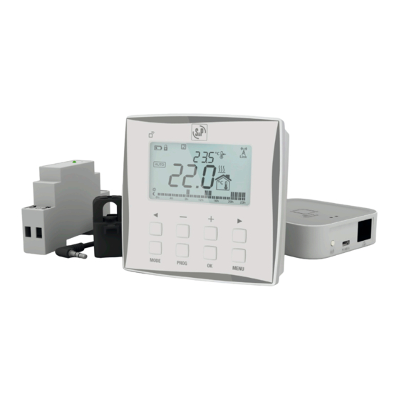
- Page 1 CONTROLES TERMOWEB TERMOWEB CONTROLS...
- Page 2 S&P. 1. ADVERTENCIAS DE SEGURIDAD • Desconecte la corriente principal de su vivienda antes de instalar el MEDIDOR TERMOWEB. • Desconecte la alimentación de la caldera antes de realizar la conexión del TERMOSTATO TERMOWEB.
- Page 3 CENTRALITA TERMOWEB. 2.1. LUCES DE LA CENTRALITA La CENTRALITA TERMOWEB muestra el estado en que se encuentra a través de sus luces LED: • Verde apagado, naranja parpadeando de forma intermitente un segundo: estado de des- cubrimiento (emparejamiento de dispositivos).
- Page 4 − 123 P − 3000 TCP 3. TERMOSTATO TERMOWEB Retire su antiguo termostato y desconecte los cables que vienen de la caldera. Separe el pa- nel frontal de la base pared presionando en la pestaña inferior y tirando de la base pared en la dirección que se ve en la ilustración.
- Page 5 FUNCIONAMIENTO DEL TERMOSTATO) hasta que aparezca el símbolo . Si la caldera no se pone en marcha desmonte el TERMOSTATO TERMOWEB, abra la tapa de la base quitando el tornillo y desconecte los cables de los bornes NO y COM para conectarlos en las conexiones NC y COM.
- Page 6 3.1.3. Descripción de los iconos de la pantalla 3.1.4. Cambio de pantallas Desde la pantalla principal del termostato se puede acceder a las distintas pantallas que nos permitirán configurar su funcionamiento. 3.1.5. Pantalla principal...
- Page 7 En el centro de la pantalla (1) se puede ver la temperatura ambiente. Se muestran al- ternándose la hora actual y la temperatura de consigna (3) sobre la pantalla principal. Si está activado el modo automático (AUTO) en la zona inferior se muestran las barras de programación (2).
- Page 8 En esta pantalla se puede cambiar la hora que se quiere modificar con las teclas y y se puede cambiar el tipo de temperatura (ahorro o confort) con las teclas + y -. Una vez modificado esa programación se puede pasar al siguiente día o periodo pulsando la tecla OK, o volver a la pantalla principal pulsando la tecla PROG.
- Page 9 Apague la alimentación de su cuadro eléctrico. Si tiene varios circuitos desconecte el magne- to térmico donde vaya a realizar la conexión. Conecte el cable de alimentación a los bornes L y N del MEDIDOR TERMOWEB. Recuerde desconectar la alimentación del magneto térmico donde hará la conexión del MEDIDOR TER- MOWEB.
- Page 10 Conecte el conector jack al conector situado en la parte superior del MEDIDOR TERMOWEB (3). Abra la pinza como se indica en la imagen y colóquela rodeando el cable principal de alimen- tación del interruptor diferencial del cuadro eléctrico (4).
- Page 11 7. EMPAREJAMIENTO 7.1. EMPAREJAMIENTO CENTRALITA TERMOWEB Una vez haya conectado a Internet la CENTRALITA TERMOWEB y la haya dado de alta en la web el http://control.termoweb.net debe emparejar los CONTROLES TERMOWEB a esta. Para ello debe poner la CENTRALITA TERMOWEB en estado de descubrimiento pulsando la tecla de emparejamiento (3).
- Page 12 7.3. EMPAREJAMIENTO MEDIDOR TERMOWEB Para emparejar el MEDIDOR TERMOWEB, realice una presión corta, con un clip (suministra- do) en el pequeño pulsador situado en la parte superior del MEDIDOR TERMOWEB. Puede comprobar que está emparejado observando el LED del MEDIDOR TERMOWEB.
- Page 13 7.4. EMPAREJAMIENTO EMISOR EMI TECH TERMOWEB Para emparejar el emisor EMI TECH TERMOWEB pulse la tecla OK durante 3 segundos hasta que aparezca el símbolo en la parte superior derecha de la pantalla del emisor. 8. CONSIDERACIONES ADICIONALES • Todos los cambios realizados en el termostato se comunican de inmediato a la centralita.
-
Page 14: Valores Por Defecto
Días laborables, CONFORT de 7h-9h, de 13h-15h, 18-23h Fin de semana, CONFORT de 9h a 23h. 10. CARACTERÍSTICAS TÉCNICAS 10.1. TERMOSTATO TERMOWEB • Dimensiones: 101x101x30 mm • Alimentación: 2 baterías AA (Alcalinas) • Salida de conmutación: 1 n. abierta, 1 n. cerrada, libres de potencial, mismo común •... - Page 15 • Tipo de ambiente: limpio • Categoría de inmunidad de sobretensión: II • Categoría de inflamable: D • Imán CISPR14: 15mA 10.2. CENTRALITA TERMOWEB • Colocación sobremesa o pared • Alimentación: adaptador de corriente externo micro USB, 5V 500mA. • Dimensiones: 80x80x22 mm •...
- Page 16 12. INFORMACIÓN PERTINENTE PARA EL DESMONTAJE, RECICLADO O ELIMINACIÓN DEL PRODUCTO AL FINAL DE LA VIDA ÚTIL En el caso de desguace de los diferentes CONTROLES TERMOWEB hay que respetar las dis- posiciones correspondientes a la eliminación o reciclaje de los materiales y componentes.
-
Page 17: Safety Warnings
ENGLISH With TERMOWEB CONTROLS you can control and set the temperature of your home and know what your electricity consumption is at any time. You can also carry out all the functions from anywhere and consult statistics and reports on your consumption, both of electricity and of heating. - Page 18 Connect the TERMOWEB CONTROL BOX to the router using the Ethernet cable (1). Connect the USB cable (2) to the TERMOWEB CONTROL BOX and to the power supply unit supplied. Wait two minutes and check by means of the LED lights on the TERMOWEB CONTROL BOX that it is communicating correctly with the router.
- Page 19 − 123 P − 3000 TCP 3. TERMOWEB THERMOSTAT Remove your old thermostat and disconnect the wires coming from the boiler. Separate the front panel from the wall bracket by pressing the lower tab and pulling away from the wall bracket in the direction shown in the illustration.
- Page 20 Place the (AA type) batteries supplied in the thermostat and mount it onto the wall bracket. NOTE: In some boilers the wires must be connected to the NC and COM terminals. To check whether this is the case, raise the TERMOWEB HEATER’s temperature in manual mode (see the HOW THE THERMOSTAT WORKS section) until the symbol appears.
- Page 21 3.1.3. Description of the icons on the screen Indicates if the unit gives heat or Month and day cold, depending on the configuration, indicators it is activated Time/setpoint Keypad lock temperature Low battery Weekdays Advanced configuration Communication status indicator Configuration menu Operating modes Indicates comfort or eco mode.
- Page 22 In the centre of the screen (1) we can see the ambient temperature. The current time and the setpoint temperature are shown alternately (3) on the home screen. If auto- matic (AUTO) mode is activated the programme bars are shown at the bottom (2). If it is in manual mode or off these bars are not shown.
- Page 23 In this screen we can change the time we want to change with the and keys and we can change the temperature type (economy or comfort) with the + and - keys. Once we have made changes to this programme, we can move on to the next day or period by pressing the OK key or returning to the home screen by pressing the PROG key.
- Page 24 Connect the power cord to the TERMOWEB METER’s L and N terminals. Remember to dis- connect the power from the thermal circuit breaker where you are going to connect the TER- MOWEB METER. Place the TERMOWEB METER in one of your electrical panel’s DIN rails that has space avai- lable. (1)
- Page 25 Connect the jack to the connector located on the top part of the TERMOWEB METER (3). Open the clamp as shown in the image and place it around the main power cord of the electrical panel’s differential switch (4).
- Page 26 TERMOWEB CONTROLS to the website. To do this we must put the TERMOWEB CONTROL BOX in discovery status by pres- sing the pairing key (3). The orange LED will start flashing intermittently.
- Page 27 7.2. PAIRING THE TERMOWEB THERMOSTAT To pair the TERMOWEB THERMOSTAT press the key at the top left of the keyboard for 5 se- conds until the symbol appears in the top right of the thermostat screen. 7.3. PAIRING THE TERMOWEB METER To pair the TERMOWEB METER, short press, with a clip (supplied), on the little button located on the top part of the TERMOWEB METER.
-
Page 28: Additional Considerations
7.4. PAIRING THE TERMOWEB EMI TECH RADIATOR To pair the EMI TECH TERMOWEB radiator, press the OK key for 3 seconds until the sym- bol appears in the top right of the radiator’s screen. 8. ADDITIONAL CONSIDERATIONS • All the changes made in the thermostat are communicated to the control box immediately. -
Page 29: Default Settings
Working days, COMFORT from 7:00 to 9:00, from 13:00 to 15:00, from 18:00 to 23:00. Weekend, COMFORT from 9:00 to 23:00. 10. TECHNICAL CHARACTERISTICS 10.1. TERMOWEB THERMOSTAT • Dimensions: 101x101x30 mm • Power supply: 2 x AA batteries (Alkaline) • Switching output: 1 n. open, 1 n. closed, potential free, same common •... - Page 30 • Surge immunity category: II • Inflammable category: D • Magnet CISPR14: 15 mA 10.2. TERMOWEB CONTROL BOX • Placement on table or wall • Power supply: external micro USB power adapter, 5 V 500 mA. • Dimensions: 80x80x22 mm •...
-
Page 31: Decommissioning / Recycling
12. INFORMATION ON DISMANTLING, RECYCLING OR DISPOSAL OF THE PRODUCT AT THE END OF ITS SERVICE LIFE If the different TERMOWEB CONTROLS are scrapped, the necessary provisions for the dispo- sal or recycling of the materials and components must be followed. - Page 32 S&P SISTEMAS DE VENTILACIÓN, S.L.U. C. Llevant, 4 Polígono Industrial Llevant 08150 Parets del Vallès Barcelona - España Tel. +34 93 571 93 00 www.solerpalau.com Ref. 1441341-1...
Need help?
Do you have a question about the TERMOWEB and is the answer not in the manual?
Questions and answers