Advertisement
Quick Links
S&P USA Ventilation Systems, LLC
6393 Powers Ave
Jacksonville, FL 32217
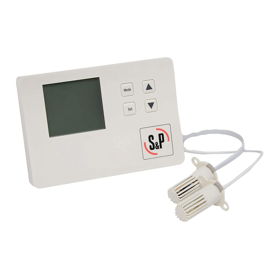
ES24V
Envirosense Ventilation Controller
The ES24V controls a ventilator to meet fresh air supply requirements
while limiting operation during periods of extreme temperature and/or
humidity.
INSTALLATION & OPERATION MANUAL
CAUTION:
1. READ AND SAVE THESE INSTRUCTIONS.
2. Before installation or maintenance, disconnect the power supply.
3. This control is for 24 VAC applications only.
4. All wiring must be done by qualified person(s) in accordance with
all applicable codes & standards.
5. Indoor Use Only
WIRING
Use Copper Conductors Only
Terminal
Type
Description
R
24Vac
Input: 24Vac input (50/60 Hz)
C
24Vac
Input: 24Vac common
G
24Vac
Input: Furnace Blower (Optional)
B
24Vac
Output: Furnace Blower (2A max) (Optional)
F+
24Vac
Output: Fresh Air Fan output + (2A max)
F-
24Vac
Output: Fresh Air Fan output - (2A max)
D+
24Vac
Output: Motorized Damper + (2A max) (Optional)
D-
24Vac
Output: Motorized Damper - (2A max) (Optional)
H+
24Vac
Output: Duct Heater output + (2A max) (Optional)
H-
24Vac
Output: Duct Heater output - (2A max) (Optional)
MOUNTING
Front Cover Removal
Insert a flathead screwdriver into the slot
on the right side of the controller and
apply gentle pressure inward and up so
that the front cover disengages from the
back cover. Pull the front cover up and to
the left.
Back Cover Mounting
Locate the control on the mounting surface being sure to allow clearance
for the necessary wiring connections. Mark the mounting hole locations and
remove the back cover from the work space. Make the stripped/labelled
wiring connections now. CAUTION: Be sure that no exposed portions of
wires are touching.
If installing onto wood, mount the back cover with the provided screws. If
installing onto drywall, drill pilot holes using a 7/32" drill bit (not provided)
and tap the provided drywall anchors into place. Mount with provided
screws. NOTE: Velcro can be used to mount the control instead of screws
if necessary.
Verify that wiring connections are correct and secure.
Align the front cover with the
back cover starting on the left
side. Push the front cover
towards the back cover in a
"hinging" motion from the left to
the right. CAUTION: Make sure
the front cover is aligned properly
with the back cover to avoid
damaging the control. Press
down until the front cover snaps
securely into place.
Sensor Mounting
The ES24V comes with a temperature sensor (26AWG, 2 wire) and
humidity sensor (6P6C, telephone wire), both 10" long. Install the sensors
at a location so that they will be exposed to the fresh air intake (ex: the
fresh air ductwork). Drill 2, 3/4" diameter holes, spaced appropriately and
install the sensors with the provided hardware. NOTE: the sensor wires can
be extended up to 300 feet without deviation. Use appropriate duct tape to
seal joints/openings as necessary.
DIMENSIONS (in)
SCREEN DIAGRAM
Operating Modes: OFF, ON, or Eco
Motorized Damper indicator
Temperature (F or C)
Fresh Air Fan indicator
Thermostat integration indicator
Duct Heater indicator
OPERATING MODES
OFF Mode: All outputs are off.
ON Mode: The Fresh Air Fan, Motorized Damper (if enabled), and
Furnace Blower (if enabled) are on continuously. The Duct Heater
will follow the user settings (see FUNCTION SETTINGS below).
Eco Mode: Eco Mode limits the Fresh Air Fan operation during
periods of extreme temperature and/or humidity. The Fresh Air
Fan, Motorized Damper (when enabled), Furnace Blower (when
enabled), and Duct Heater (when enabled) will follow the user
settings when the outside air temperature/humidity is within the
user set limits (see FUNCTION SETTINGS below).
The Fresh Air Fan will run for the user set amount of time/hour
while the temperature/humidity limits are within range. The
temperature/humidity sensors evaluate the fresh air conditions
every 10 seconds. While the fresh air temperature/humidity is
within the user set limits, the Fresh Air Fan/accessories will run
per the user settings. When the fresh air temperature/humidity
exceeds the user set limits, the Fresh Air Fan/accessories will turn
off and engage a timer. The timer will run the fan for 5 minutes
every 15 minutes in order to meet code requirements. NOTE: the
Furnace Blower (if enabled) will not run during this check
procedure to prevent cycling. The fan will continue this check
procedure until the temperature/humidity limits are within the user
set limits.
If Enabled (in SETUP):
The Furnace Blower will be on: any time there is a call from "G"
Input or any time the Fresh Air Fan is on (excluding the check
procedure above).
The Motorized Damper will be on anytime the Fresh Air Fan is on.
The Duct Heater will be on any time the Fresh Air Fan is on and
the set point > room temperature +2°F.
(Motorized Damper, Furnace Blower, and Duct Heater are
required to be enabled in SETUP)
BUTTONS
Keys
Description
Mode
Select the operating mode
Set
Confirm settings
▲
Increase settings
▼
Decrease settings
Relative Humidity %
Advertisement

Subscribe to Our Youtube Channel
Related Manuals for S&P ES24V


Summary of Contents for S&P ES24V
- Page 1 Temperature (F or C) installing onto drywall, drill pilot holes using a 7/32” drill bit (not provided) The ES24V controls a ventilator to meet fresh air supply requirements and tap the provided drywall anchors into place. Mount with provided while limiting operation during periods of extreme temperature and/or screws.
- Page 2 SETUP FACTORY RESET Press and hold [MODE] for 3 seconds to enter setup mode. Press and hold [▲]&[▼] buttons in OFF mode for ~5 seconds to reset the control to factory settings. will be displayed on the screen when complete. FEATURES ◆...
Need help?
Do you have a question about the ES24V and is the answer not in the manual?
Questions and answers