Table of Contents
Advertisement
Quick Links
CONTENTS
INTRODUCTION . . . . . . . . . . . . . . . . . . . . . . . . . . . . . . 1
Specifications . . . . . . . . . . . . . . . . . . . . . . . . . . . . . . . 2
Inputs . . . . . . . . . . . . . . . . . . . . . . . . . . . . . . . . . . . . . . 3
• POWER SUPPLY
Outputs . . . . . . . . . . . . . . . . . . . . . . . . . . . . . . . . . . . . 3
WIRING THE WIFI THERMOSTAT . . . . . . . . . . . . . . . 3
To Wire Duel Fuel Systems and Furnace /
AC Systems . . . . . . . . . . . . . . . . . . . . . . . . . . . . . . . . . 3
To Wire Hotel Systems . . . . . . . . . . . . . . . . . . . . . . . . 6
(Sensor or Contacts) . . . . . . . . . . . . . . . . . . . . . . . 6
To Wire for BACnet Communication . . . . . . . . . . . . . 6
FOR ENHANCED ACCESS . . . . . . . . . . . . . . . . . . . 7
Using the WIFIStat Website or App . . . . . . . . . . . . . . 7
GETTING TO KNOW THE USER INTERFACE . . . . . . 8
Dormant Screen . . . . . . . . . . . . . . . . . . . . . . . . . . . . . 8
Home Screen . . . . . . . . . . . . . . . . . . . . . . . . . . . . . . . . 8
Occupancy/Enter PIN Screen . . . . . . . . . . . . . . . . . . . 8
Changing the Setpoints . . . . . . . . . . . . . . . . . . . . . . . 9
Changing the Fan . . . . . . . . . . . . . . . . . . . . . . . . . . . . 9
Changing the Mode . . . . . . . . . . . . . . . . . . . . . . . . . . . 9
To Adjust Date and Time . . . . . . . . . . . . . . . . . . . . . 10
To Adjust Occupancy Settings . . . . . . . . . . . . . . . . 11
To Adjust the Display Settings . . . . . . . . . . . . . . . . 12
To Adjust the Banner Text . . . . . . . . . . . . . . . . . . . . 13
USING INSTALLER SETTINGS . . . . . . . . . . . . . . . . . 14
To Set Up BACnet . . . . . . . . . . . . . . . . . . . . . . . . . . . 18
To Test the HVAC System . . . . . . . . . . . . . . . . . . . . 21
To restore factory default settings . . . . . . . . . . . . . 21
SETTING UP WI-FI . . . . . . . . . . . . . . . . . . . . . . . . . . . 22
TIMERS, MEMORY, AND DEADBAND . . . . . . . . . . . 22
FAULTS AND SYSTEM EVENTS . . . . . . . . . . . . . . . 23
APPENDIX A: BACNET POINTS LIST . . . . . . . . . . . 24
Manufacturer reserves the right to discontinue, or change at any time, specifications or designs without notice and without incurring obligations.
Catalog No. 04-53500408-01
Installation Instructions
33WIFISTAT43FX
Printed in U.S.A.
Form No. IIK-33WIFISTATFX-01
APPENDIX B: BACNET FUNCTIONALITY . . . . . . . .27
APPENDIX C: BACNET CONSTRAINTS . . . . . . . . . .27
Page
INSTANCE RANGES . . . . . . . . . . . . . . . . . . . . . . . . . .27
APPENDIX E: BACNET OBJECT NOTES . . . . . . . . .28
The Wi-Fi thermostat is a thermistor-based wireless thermostat
that can sense a 10K Type II OAT or a remote space or return air
sensor and can control up to 4 heating and 3 cooling stages.
The 33WIFISTAT43FX Wi-Fi thermostat has:
•
Space and remote temperature sensing
•
Space and remote humidity sensing
•
BACnet MS/TP communications
•
Wi-Fi connectivity
The Wi-Fi thermostat package includes:
•
Thermostat
•
Mounting Hardware - two screws with drywall anchors
and one security screw
•
Quick Start Guide
Some of the features:
•
Control of heating, cooling, and fan solid state 24 Vac
outputs
•
Space temperature sensing (> 0.5°F accuracy from 60°F to
90°F)
•
Outdoor temperature sensing using a 10K @ 25°C J Curve
(type II) thermistor connected to T and C terminals or Wi-
Fi outdoor temperature, available by GPS location ser-
vices, determined when the thermostat is installed
•
Humidity sensing and control
•
Remote humidity sensing from a 33ZCSENDRH-02 Hu-
midity Duct Sensor or 33ZCSENSRH-02 wall sensor
•
Remote CO
2
•
Wi-Fi connectivity (supports 802.11 a/b/g/n standards and
utilizes a Broadcom chipset)
•
Cloud Connectivity using the WIFIStat mobile app (iOS
and Android)
•
Optimized installation ("finger friendly" spring-loaded
connectors that accept 16 to 24 AWG wire and NO screw-
driver required for wire insertion and removal)
•
Optimized boot time (5 seconds total boot time until tem-
perature displays and thermostat is fully operational)
•
4.3 in. segment display
•
Thirteen touch points for display buttons
•
OTA
functionality
specifications
Wi-Fi Thermostat
INTRODUCTION
sensing from a 0-10 vdc or 4-20 mA sensor
(reprogrammable
Pg 1
2-24
via
Wi-Fi)
Replaces: NEW
Advertisement
Table of Contents

Related Manuals for Carrier 33WIFISTAT43FX


Summary of Contents for Carrier 33WIFISTAT43FX
-
Page 1: Table Of Contents
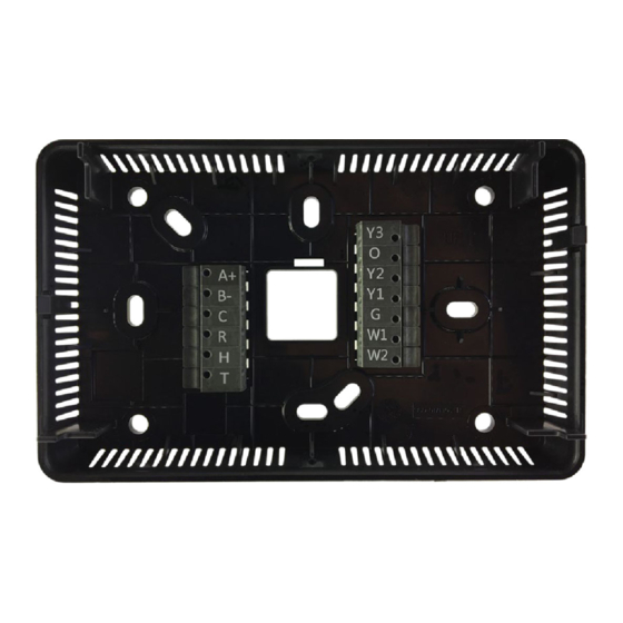
• REMOTE TEMPERATURE SENSOR sensor and can control up to 4 heating and 3 cooling stages. • REMOTE HUMIDITY OR CO2 SENSOR (0-10 VOLT OR 4-20 MA) The 33WIFISTAT43FX Wi-Fi thermostat has: • SPACE HUMIDITY SENSOR • Space and remote temperature sensing Outputs . -
Page 2: Specifications
Heat only with gas heat (up to 2 stages of heating) Specifications • Heating See Fig. 1 — for available Inputs and Outputs. - W1 - first stage heat - W1 + W2 - second stage heat Power requirements 24 Vac 50/60 Hz @ 6VA Network Wi-Fi connectivity supports Wi-Fi: 802.11 a/b/ Heat only with electric heat (up to 3 stages of heating) -
Page 3: Inputs
SPACE HUMIDITY SENSOR Table 1 — Definitions The humidity is read via synchronous communications from a Sensirion SHT21 Humidity and Temperature Sensor. The The space temperature is greater than the Heat Demand Sensirion humidity is accurate to ± 2% relative humidity between heat setpoint (HEAT TO setting). - Page 4 Fig. 3 — Dual Fuel Systems, Single Stage Furnace, Fig. 6 — Furnace / AC Systems, Single-Stage 2-Stage HP Furnace, 2-Stage AC Fig. 4 — Dual fuel systems, 2-Stage Furnace, Fig. 7 — Furnace/AC System, 2-Stage Furnace, 2-Stage HP 2-Stage AC Fig.
-
Page 5: To Wire An Air Handler With Heat Pump Or With Ac
To Wire an Air Handler with Heat Pump or with See Fig. 9-15 for wiring details. Fig. 12 — Air Handler / AC Systems, Single-Stage Air Handler, Single Stage AC Fig. 9 — Air Handler / Heat Pump, Single-Stage Air Handler, Single-Stage HP Fig. -
Page 6: To Wire Hotel Systems
• • • • Occupancy contacts • Econ Fault WIRING SPACE TEMPERATURE SENSOR AVERAGING See Fig 17 and 18 for space temperature averaging wiring details. Fig. 15 — Air Handler / AC Systems, Single-Stage Air Handler, 3-Stage AC To Wire Hotel Systems Fig. -
Page 7: Registering And Setting Up A Mobile Device For Enhanced Access
You can: • Monitor the thermostat operation CAUTION • Set up occupied and unoccupied (holiday) schedules Maintain the same polarity. • Adjust setpoints • Share thermostat access with other users REGISTERING AND SETTING UP A MOBILE • Create groups of thermostats that you have registered DEVICE FOR ENHANCED ACCESS •... -
Page 8: Getting To Know The User Interface
The banner scrolls through date and time, humidity, outdoor air Table 2 — Screen Functions temperature, if configured, and any active faults or system events. The room temperature is prominently displayed. SCREENS USE TO There are no buttons on this screen, but the 13 touch locations are SETPOINTS Adjust the occupied and unoccupied setpoints by active, so when the display is touched, the thermostat transitions to... -
Page 9: Changing The Setpoints
program schedule using the OCC/UNOCC button modifies both the setpoint values and the fan setting. A program schedule override is treated the same whether you manually change the setpoints or use the OCC/UNOCC button. When an override is active, the center button label changes to RESUME SCHEDULE, the period icon above the space temperature is not displayed, and the amount of time remaining in the override is displayed in the banner. -
Page 10: Using The Menu For Advanced Features
5-second mode button). See Timers for additional descriptions of • You must SAVE to store the current value and return to the the MINIMUM OFF timer and the MINIMUM ON timer. SELECT screen. NOTE: Some modes may not be available, based on the •... -
Page 11: To Adjust Occupancy Settings
To Adjust Occupancy Settings Table 4 — Occupancy Settings (cont) See Table 4 for a list of occupancy settings and specifications. SETTING DEFAULT/RANGE OCC HEAT—The heat setpoint during occupied 70° F Table 4 — Occupancy Settings periods 50° to 88° F NOTES: •... -
Page 12: To Adjust The Display Settings
To Adjust the Display Settings See Table 5 for a list of display settings and specifications. Table 5 — Display Settings SETTING DEFAULT/RANGE CLCK (Click) SOUND EFFECT—Select the sound feedback when you press a button. Off, CLCK (Click), Beep BACKLIGHT—There are two backlight settings, one for interacting with the thermostat and another for the dormant screen. -
Page 13: To Adjust The Banner Text
The FAN STATUS, HEAT SETPOINT, and COOL To Adjust the Banner Text SETPOINT selections only apply to the dormant screen banner These settings allow you to customize the information shown on because this information is already displayed in other areas of the the top banners of the home and dormant screens. -
Page 14: Using Installer Settings
• The SELECT button allows the installer to change the USING INSTALLER SETTINGS value of the setting. To reach the Installer Settings screens, set the mode to OFF and • Press DEFAULT to set the value to the factory default. press and hold the MENU button for 5 seconds. - Page 15 Table 7 — Installer Setting Screen Options (cont) SETTING DEFAULT/RANGE F or C UNITS—Sets the temperature units to either F (Fahrenheit) or C (Celsius). SMART RECOVERY — Transitions the conditioned space from one programmable temperature period to the next with 1°F increments of the heating setpoint or 1°F decrements of the cooling setpoint, so that by the time the next period starts, the setpoints are at the desired temperature.
- Page 16 Table 7 — Installer Setting Screen Options (cont) SETTING DEFAULT/RANGE LOW HEAT LOCKOUT TEMPERATURE—Sets an outdoor air temperature below which low speed compressor heating is locked out. Below the specified air temperature, all heating demands that use the compressor use high speed compressor heating.
- Page 17 Table 7 — Installer Setting Screen Options (cont) SETTING DEFAULT/RANGE HP LOCKOUT—Sets an outdoor temperature below which the heat pump does not operate. If set to OFF, the heating equipment cycle always starts with the heat pump, regardless of the outdoor air temperature. If a lockout temperature is selected and the outdoor air temperature is less than the selected temperature, the heating cycle is 5°...
-
Page 18: To Set Up Bacnet
Table 7 — Installer Setting Screen Options (cont) SETTING DEFAULT/RANGE HUM OUTPUT—Select which output relay to use for the humidifier. The choices only include outputs that are not already assigned to another function. The output that is selected (Y3, O/B or W2) is used to control the humidifier equipment. NOTE: HUM OUTPUT is only available if the HUMIDIFIER setting is YES. - Page 19 Table 8 — BACnet Settings (cont) SETTING DEFAULT/RANGE MSTP BAUD RATE—Set the baud rate for the BACnet MS/TP communications to one of the following values: 76.8K 9600, 19.2K (19200), 38.4K (38400), 76.8K (76800) or 115k (115200). The BACnet MS/TP baud rate must be set 9600 to match the other devices on the BACnet MS/TP network.
- Page 20 Table 8 — BACnet Settings (cont) SETTING DEFAULT/RANGE NET GP Y3 MODE—Select Network General Purpose Output Y3 for control over the BACnet network. Off (disabled) Setting the mode to: Off (disabled) • OFF (disabled) sets the Present Value of the BACnet object to inactive and read-only and the corresponding ACTV (energized active) output relay will be in a de-energized state.
-
Page 21: To Test The Hvac System
To Test the HVAC System Table 9 — Factory Default Settings The installer uses this setting to test the HVAC system. Press SELECT to open INSTALLER TEST, see Fig. 29. SCREEN FACTORY DEFAULTS HEATING EQUIP TYPE NOTE: The HOME and SELECT buttons are replaced with HEATING EQUIP STAGES MODE and CANCEL buttons. -
Page 22: Setting Up Wi-Fi
MAC address SETTING UP WI-FI The MAC address is a unique 12-digit identifier associated with To display the SETUP WI-FI screen, press: the Wi-Fi radio chip that contains the letters A through F and the • if the thermostat is connected to a Wi-Fi network numbers 0 through 9. -
Page 23: Faults And System Events
• Server Connectivity Events FAULTS AND SYSTEM EVENTS • Non-Volatile Memory Faults The faults and system events are displayed in the home and • Temperature Faults dormant screen banners. See Table 10. Faults and system events include: The faults and system events display in the banner while fault condition exists. -
Page 24: Appendix A: Bacnet Points List
APPENDIX A: BACNET POINTS LIST BACNET POINT NAME POINT ACCESS UNITS BACNET POINT NAME OBJECT ID Indoor Space Temperature WRITE_WHEN_OOS DEGREES_FAHRENHEIT ID_SPACE_TEMP AI:100 Indoor Space Humidity WRITE_WHEN_OOS PERCENT_RELATIVE_HUMIDITY ID_SPACE_HUM AI:101 Indoor Space CO2 WRITE_WHEN_OOS PARTS_PER_MILLION ID_SPACE_CO AI: 102 Remote Space Temperature READ_ONLY DEGREES_FAHRENHEIT REM_SPACE_TEMP... - Page 25 APPENDIX A: BACNET POINTS LIST (CONT) BACNET POINT NAME POINT ACCESS UNITS BACNET POINT NAME OBJECT ID Humidifier Out Status READ_ONLY 0=OFF HUM_OUT BV:209 1=ON Dehumidifier Out Status READ_ONLY 0=OFF DEHUM_OUT BV:210 1=ON Network General Purpose Out Y3 READ_WRITE 0=OFF NET_GP_Y3_OUT BV:211 1=ON...
- Page 26 APPENDIX A: BACNET POINTS LIST (CONT) BACNET POINT NAME POINT ACCESS UNITS BACNET POINT NAME OBJECT ID NOT CONNECTED TO ROUTER READ_ONLY 0=INACTIVE RTR_CONN_FAIL BV:913 1=ACTIVE WIFI HARDWARE FAULT READ_ONLY 0=INACTIVE WIFI_CONF_FAIL BV:914 1=ACTIVE ECONOMIZER FAULT READ_ONLY 0=INACTIVE ECON_FAULT BV:915 1=ACTIVE LOCKOUT-5 BAD PIN ENTRIES READ_ONLY...
-
Page 27: Appendix B: Bacnet Functionality
APPENDIX A: BACNET POINTS LIST (CONT) BACNET POINT NAME POINT ACCESS UNITS BACNET POINT NAME OBJECT ID Analog Input Scaling GATED_WRITE 1=2-10V ANALOG_IN_SCALE MSV:513 (4-20mA w/ext 500 Ohm) 2=0-10V APPENDIX B: BACNET FUNCTIONALITY APPENDIX C: BACNET CONSTRAINTS BACnet Communication UTC Time Synchronization BACnet MS/TP If the device is to support UTCTimeSynchronization, time syncs with Local Time is disabled to avoid ambiguity, Daylight Saving... -
Page 28: Appendix E: Bacnet Object Notes
3 outputs are left unassigned, they can be configured to be net- work controlled outputs by changing their mode from Fig. A — Multiplexed Inputs © 2024 Carrier Manufacturer reserves the right to discontinue, or change at any time, specifications or designs without notice and without incurring obligations. Catalog No. 04-53500408-01 Printed in U.S.A.
Need help?
Do you have a question about the 33WIFISTAT43FX and is the answer not in the manual?
Questions and answers