Table of Contents
Advertisement
Quick Links
Advertisement
Table of Contents

Summary of Contents for Cervis Wireless smaRT BU-H16R Series
- Page 1 BU-xH16R 900 MHz and 2.4 GHz Base Units Manual U095.1.1 Ó2023 Cervis, Inc.
- Page 2 SmaRT BU-xH16R This document is the property of Cervis, Inc. and cannot be copied, modified, e-mailed, or reproduced without the express prior written consent of Cervis, Inc. Cervis, Inc. reserves the right to change this manual or edit, delete, or modify any information without prior notification.
-
Page 3: Table Of Contents
List of Figures ..........................i List of Tables ..........................i Definitions/Notes ......................... ii Cervis, Inc. Safety Precautions ....................1 1.0 SmaRT BU-xH16R Base Unit and Handheld Remote Control ......... 2 2.0 SmaRT BU-xH16R Base Unit ....................3 2.1 Base Unit Installation ....................... 4 2.2 SmaRT BU-xH16R Wiring Information ................ -
Page 4: Definitions/Notes
SmaRT BU-xH16R Definitions/Notes Associate Mode where by SmaRT handhelds and base units are paired for operation (IDs exchanged). This mode is used to commission spare handhelds or base units. DSSS Direct Sequence Spread Spectrum; an advanced wireless communication technology. Dissociate or Disassociate The process of decommisioning a handheld from a base unit ID memory. -
Page 5: Cervis, Inc. Safety Precautions
Base Units Manual DRAFT Cervis, Inc. Safety Precautions ü Read and follow all instructions. ü Failure to abide by Safety Precautions may cause equipment failure, loss of authority to operate the equipment, and personal injury. ü Use and maintain proper wiring. Follow equipment manufacturer instructions. -
Page 6: Smart Bu-Xh16R Base Unit And Handheld Remote Control
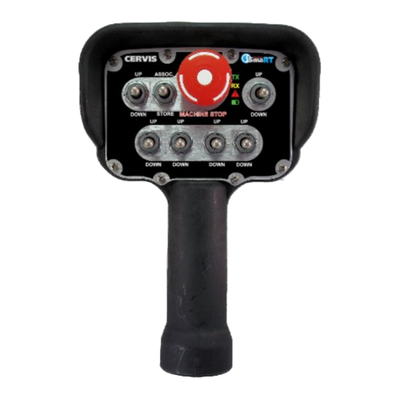
SmaRT BU-xH16R SmaRT BU-xH16R Base Unit and Handheld Remote Control Note: The “x” in BU-xH16R represents both 900 MHz (9) and 2.4 GHz (2) base units. A standard SmaRT BU-xH16R remote control system consists of a SmaRT BU-xH16R base unit, a SmaRT handheld remote control unit, and the cable(s) that connect the base unit to the controlled machinery. -
Page 7: Smart Bu-Xh16R Base Unit
Capable of communicating with up to eight SmaRT handheld remotes • License free 900 MHz or 2.4 GHz DSSS technology • Direct line-of-sight extended range of up to 1,000 feet (300 m) • Sixteen independent Form A control relay outputs divided into two banks of eight Ó2023 Cervis, Inc. -
Page 8: Base Unit Installation
Make sure that the machine the base unit will be attached to is disabled during installation. Use the configuration diagrams supplied by Cervis, Inc. to guide you in mounting the base unit and connecting your wiring harness cables. Base unit mounting is left much to your discretion with the following guidelines: •... -
Page 9: Figure 4. P1 And P2 Cable Wiring Assignments
(11) K5 (12) K15 Figure 4. P1 and P2 Cable Wiring Assignments CAUTION To protect against short circuits, be sure the ends of all unused wires are insulated when making connections. Figure 5. Dual Connectors/Pin Numbers (enhanced) Ó2023 Cervis, Inc. -
Page 10: Figure 6. P1 And P2 Cable Field Wiring Layout
SmaRT BU-xH16R Figure 6. P1 and P2 Cable Field Wiring Layout U095.1.1... -
Page 11: External Protection Devices For Relay Contacts
When using contactors or solenoids with SmaRT systems, it is advisable to use external protective devices by connecting them across the coils as shown in the examples below using MOVs. Typical MOV Figure 7. Suggested MOV Wiring Across the Contactor Coils Ó2023 Cervis, Inc. -
Page 12: Base Unit Troubleshooting
Interpretation – Recommendation ü Is input power present? Power LED not active ü Check input power polarity. Indicates an internal component failure. Contact Cervis, Inc. Service Power LED Red or Green department. ü Check for obstructions preventing line-of-sight transmission. ü... -
Page 13: Specifications
Inductive: 2 A at 250 VAC or 30 VDC 10 A max per bank with Serial COM 20 A max per bank without Serial COM Bank A Relays K1 – K8 Bank B Relays K9 – K16 Protocol SAE J1939 Ó2023 Cervis, Inc. -
Page 14: Appendix A: Bu-Xh16R Hardware Options
SmaRT BU-xH16R Appendix A: BU-xH16R Hardware Options Table 4. BU-xH16R Hardware Options Serial Model Frequency RF Pwr. Input Pwr. Antenna Port Sup. BU-9H16R-INT-LVD 900 MHz 10 mW 7–32 VDC Internal BU-9H16R-INT-LVD-CANP 900 MHz 10 mW 7–32 VDC Internal BU-9H16R-INT-LVD-NOS 900 MHz 10 mW 7–32 VDC Internal... -
Page 15: Appendix B: Bu-Xh16R Wiring Harness Options
Note: All SmaRT base unit agency LABEL ID labels are located in the area shown. The base unit label position is identical for both internal antenna and external antenna base units. Figure 8. Agency Identification Label Locations Ó2023 Cervis, Inc. - Page 16 SmaRT BU-xH16R U095.1.1...


Need help?
Do you have a question about the Wireless smaRT BU-H16R Series and is the answer not in the manual?
Questions and answers