Table of Contents
Advertisement
Quick Links
Advertisement
Table of Contents

Subscribe to Our Youtube Channel
Summary of Contents for Cervis Warrior MU-X6E Series
- Page 1 ™ MU6E Receiver Manual U107.1.0 2018 Cervis, Inc.
- Page 2 Warrior MU6E This document is the property of Cervis, Inc. and cannot be copied, modified, e-mailed, or reproduced without the express prior written consent of Cervis, Inc. Cervis, Inc. reserves the right to change this manual or edit, delete, or modify any information without prior notification.
-
Page 3: Table Of Contents
Table of Contents .......................... i List of Figures ..........................i List of Tables ..........................i Definitions/Notes ......................... iii Cervis, Inc. Safety Precautions ....................1 1.0 Warrior MU6E ........................2 1.1 Warrior MU6E Receiver ....................2 2.0 Warrior MU6E System PCBs ....................3 2.1 MU6E Main PCB ........................ - Page 4 Warrior MU6E Table 4. MU6E Power Configurations ...................9 Table 5. MU6E DIP Switch 7-8 Configuration Status ..............10 Table 6. MU6E Receiver Specifications ..................12 Table 7. Warrior System Options ....................14 U107.1.0...
-
Page 5: Definitions/Notes
When a handheld transmitter takes control of a receiver for operation. Radio Frequency (wireless) RF TX/RX Wireless transmission (TX) and reception (RX) of data. Transmitter Handheld or portable RF control unit. Warrior Receiver Transmitter-controlled unit mounted to the crane or machine. 2018 Cervis, Inc. -
Page 7: Cervis, Inc. Safety Precautions
Receiver Manual Cervis, Inc. Safety Precautions Read and follow all instructions. Failure to abide by Safety Precautions may cause equipment failure, loss of authority to operate the equipment, and personal injury. Use and maintain proper wiring. Follow equipment manufacturer instructions. -
Page 8: Warrior Mu6E
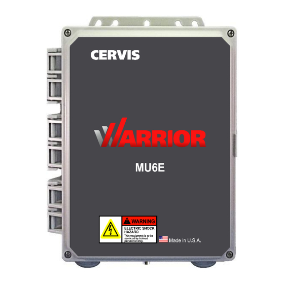
The MU6E is self-contained and can be configured with various input/output (I/O) modules accommodating a wide range of I/O requirements. The MU6E accepts control commands from the full range of Cervis, Inc. Warrior transmitters, including the multi-joystick, multi-axis Warrior Console Box (CB). -
Page 9: Warrior Mu6E System Pcbs
The main PCB consists of the series M-STOP force-guided relays, association relay, start relay, the requisite connectors, and the main processors. The board fuse part number is P/N: Little Fuse 0217002.H (250VAC, 5A). PROCESSORS PUSHBUTTON Figure 2. MU6E Main PCB 2018 Cervis, Inc. -
Page 10: Dip Switch Configuration
Green transmitter/receiver association is UNLOCKED (1) or LOCKED (0). Most receivers ship from Cervis, Inc. with the association DIP switch locked (0). This switch can be manually and virtually unlocked to associate additional transmitters, if necessary (see Section 4.3). Figure 3. MU6E DIP Switch... -
Page 11: Mu6E Power Card
The MU6E power card accepts an input voltage that powers the unit. This expansion card accepts 110VAC to 220VAC at 50Hz to 60Hz. Line Fuse P/N: Little Fuse 0217002.H (250VAC, 2A). Figure 4. MU6E HVA Power Card 2018 Cervis, Inc. -
Page 12: Mu6E Relay Card
Warrior MU6E 2.3 MU6E Relay Card Each relay card consists of eight Form A relays capable of conducting 8A max @ 250VAC; each bank of relays is fused at 5A. Each relay is commanded by a slave processor that resides on the relay card. -
Page 13: Mu6E Analog Card
D2. Table 3 describes their functions. Figure 6. MU6E Analog Card Table 3. MU6E Analog Card Diagnostic LEDs Name LED State Description Transmit Fast Blinking Indicates messages sent to master processor Health Blinking Unit OK, normal processor operation 2018 Cervis, Inc. -
Page 14: Mu6E Mounting
To avoid injury, disable the machine that the receiver will be attached to before installation. Use the configuration diagrams that Cervis, Inc. supplied to guide you in mounting the receiver and connecting your wire harness. Receiver mounting is left much to your discretion with the following guidelines: ... -
Page 15: Mu6E Power
MU6E-HVA High Voltage AC 110 to 220 V In DC applications, an external AC-to-DC converter must be used; consult Cervis, Inc. Applications, if needed. 3.2 MU6E External Antenna MU6E units come with a 900MHz external antenna that attaches to the receiver using the external unit connector. -
Page 16: Warrior Mu6E Operation
4.3 Additional Warrior Programming Features 4.3.1 Horn/Light (Associate) Relay Each Warrior system has a Horn/Light relay. Cervis, Inc. recommends properly wiring this relay to some type of indicating device—such as a horn or light—that is easily recognized when activated. When wired correctly, the operator will be alerted during the association process, and the receiver communicating can easily be identified. -
Page 17: Low Battery Mode
As part of the association process, the receiver will become nominated. The Horn/Light relay will cycle on and off while the receiver is nominated. This notifies the operator that the correct machine has been selected. When the association process is completed, this relay stops cycling. 2018 Cervis, Inc. -
Page 18: Mu6E Receiver Specifications
Warrior MU6E 5.0 MU6E Receiver Specifications Table 6. MU6E Receiver Specifications Item Description Power 110 to 220 VAC @ 50–60 Hz Environment Operating Temp -40°C to 75°C* (-40°F to 167°F) Storage Temp -40°C to 80°C (-40°F to 176°F) Humidity 0–95% non-condensing Radio Frequency 906–924 MHz @ 100mW... -
Page 19: Appendix A: Exposure To Radio Frequency Energy
Required Training All installers and operators of host applications that include an SRF310 radio transmitter (RT) module must be trained to use proper RF safety precautions as presented in this section. 2018 Cervis, Inc. -
Page 20: Appendix C: Warrior System Options
Warrior MU6E Appendix C: Warrior System Options The following table lists available system options. Table 7. Warrior System Options Item # Description J5-02 10' antenna extension cable (TNC to bulkhead mount) J5-07 3' antenna extension cable (TNC to bulkhead mount) J5-12 Antenna bracket w/ isolation washers 15114311... - Page 21 Receiver Manual www.cervisinc.com Visit our Web site at: 2018 Cervis, Inc. All rights reserved. Content is subject to change without notice. 2018 Cervis, Inc.


Need help?
Do you have a question about the Warrior MU-X6E Series and is the answer not in the manual?
Questions and answers