Table of Contents
Advertisement
Quick Links
Advertisement
Table of Contents

Related Manuals for Cervis Warrior MU-X15 Series


Summary of Contents for Cervis Warrior MU-X15 Series
- Page 1 ™ MU-X15 System Manual U100.4.0 ©2019 Cervis, Inc.
- Page 2 This document is the property of Cervis, Inc. and cannot be copied, modified, e-mailed, or reproduced without the express prior written consent of Cervis, Inc. Cervis, Inc. reserves the right to change this manual or edit, delete, or modify any information without prior notification.
-
Page 3: Table Of Contents
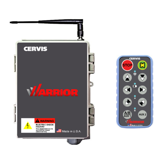
Table of Contents .......................... i List of Figures ..........................ii List of Tables ..........................ii Definitions/Notes .......................... 1 Cervis, Inc. Safety Precautions ....................2 1.0 Warrior MU-X15 System ...................... 3 1.1 Warrior MU-9X15 Receiver ....................3 1.2 Warrior MU-X15 HH2S-9XW10 Handheld Remote ............4 2.0 Warrior MU-9X15 ........................ - Page 4 List of Figures Figure 1. Warrior MU-X15 System Receiver and Handheld Remote ........3 Figure 2. Warrior MU-X15 HH2S-9XW10 Handheld Remote .............4 Figure 3. Bank Configuration.......................5 Figure 4. MU-9X15 LED Indicators and Relay Locations ............6 Figure 5. MU-9X15 Mounting Dimensions ..................8 Figure 6.
-
Page 5: Definitions/Notes
System Manual Definitions/Notes Association: When a handheld is programmed with a receiver’s identification (ID) during the Association process. Pairing: When a handheld takes control of a receiver for operation. DSSS: Direct Sequence Spread Spectrum; an advanced wireless communications technology. Warrior Receiver: “Receiver” mounted to the crane or machine. Line of Sight (aka Direct Line of Sight): Term used to describe radio frequency (RF) communication where the pathway between units is clear of physical obstacles such as walls, earth, and other obstructions. -
Page 6: Cervis, Inc. Safety Precautions
Cervis, Inc. Safety Precautions ✓ Read and follow all instructions. ✓ Failure to abide by Safety Precautions may result in equipment failure, loss of authority to operate the equipment, and personal injury. ✓ Use and maintain proper wiring. Follow equipment manufacturer instructions. -
Page 7: Warrior Mu-X15 System
Designed to ICS 8 NEMA Crane Specification • Eight DIP switches allow for configurability • High VAC, Low VAC, and DC input ranges available • Operating temperature: –40°C to +70°C (–40°F to +158°F) • Storage temperature: –40°C to +80°C (–40°F to +176°F) ©2019 Cervis, Inc. -
Page 8: Warrior Mu-X15 Hh2S-9Xw10 Handheld Remote
ID in its memory. One or more handhelds are associated with the receiver at Cervis, Inc. before it is shipped. Users use the Association process described in Section 4.0 to change the ID in a handheld memory. See Section 4.4 (Factory Reset) to clear the handheld memory so that it will not control any receiver. -
Page 9: Warrior Mu-9X15
2.1 Input Voltages Depending on the model, the MU-9X15 accepts the following input voltages: • 110 to 220 VAC at 50–60 Hz (High VAC) • 10 to 28 VAC at 50–60 Hz (Low VAC) • 9 to 36 VDC ©2019 Cervis, Inc. -
Page 10: Mu-9X15 Diagnostic Leds
2.2 MU-9X15 Diagnostic LEDs The MU-9X15 has three system status LEDs, 16 relay status LEDs, and four power LEDs that can be used as diagnostics tools (see Table 1). The MU-9X15 has one internal LED indicator used for association and health status visible from outside the enclosure. The strobe LED can be shut off for one hour by pressing the shutoff switch (see the circle in Figure 4) and will reactivate after either one hour has passed or Association (Section 4.2) is performed. -
Page 11: Mu-9X15 Mounting
Disable the machine on which the receiver is to be attached before installation to avoid injury. Use the configuration diagrams supplied by Cervis, Inc. to guide you in mounting the receiver and connecting your wire harness. Receiver mounting is left much to your discretion with the following guidelines: •... -
Page 12: Figure 5. Mu-9X15 Mounting Dimensions
Figure 5. MU-9X15 Mounting Dimensions U100.5.0... -
Page 13: Mu-9X15 Power
Antenna extensions are available in 3-, 10-, and 25-foot lengths. Available Extension Cables: 25' J5-13 10' J5-02 3' J5-07 External Antenna BB3-06 Figure 6. MU-9X15 900 MHz External Antenna and Optional Extension Cables ©2019 Cervis, Inc. -
Page 14: Mu-9X15 Cable And Field Wiring
2.6 MU-9X15 Cable and Field Wiring Note : The control cable is individually marked on the insulation of each wire. Negative VDC (–VDC) should be connected directly to the power supply negative terminal. Figure 7. MU-9X15 Wiring Diagram U100.5.0... -
Page 15: Mu-9X15 Fuse Information
Table 5. DIP Switch 3: Applies to All Modes and All Transmitters Name Definition AB BOTH/OFF HH: Cycle pattern is A, B, Both. MCB: Middle position of A/B switch is BOTH. HH: Cycle pattern is A, B, Off. MCB: Middle position of A/B switch is OFF. ©2019 Cervis, Inc. -
Page 16: Table 6. Dip Switch 4: Applies To Hh, Only Applies To Mode 00 Or 01
Table 6. DIP Switch 4: Applies to HH, Only Applies to Mode 00 or 01 Name Definition AB CYC/IND HH: Button 9 cycles A/B (See AB BOTH/OFF). MCB: No effect. HH: Button 9 activates A, button 10 activates B, NO AUX (see AB MOM/LAT) MCB: No effect. -
Page 17: Mu-9X15 Relay-To-Mode Output Assignments
HD2 – Hoist Down second Speed* TF2 – Trolley Forward Second Speed* TR2 – Trolley Reverse Second Speed* R – 4 F – 4 Axis Reverse Axis Forward 2 – 4 Axis Second Speed *Used in four wire applications. ©2019 Cervis, Inc. -
Page 18: Warrior Mu-X15 Handheld Remote (Hh2S-9Xw10)
3.0 Warrior MU-X15 Handheld Remote (HH2S-9XW10) The HH2S-9XW10 handheld is a small, compact handheld remote control that interfaces with Warrior MU-9X15 receiver. The HH2S-9XW10 is made up of ten 2-step actuators. The HH2S- 9XW10 uses two AAA cell batteries for power. The handheld remote enclosure is constructed of rugged polycarbonate designed to meet an ingress protection rating of IP55, according to IEC 60529. -
Page 19: Hh2S-9Xw10 Battery Installation
Note: Discard expired batteries according to local regulations. Figure 10. HH2S-9XW10 Battery Installation Be sure to observe proper polarity when placing batteries in the handheld battery compartment. ©2019 Cervis, Inc. -
Page 20: Hh2S-9Xw10 Battery Warning And Shutdown
3.2 HH2S-9XW10 Battery Warning and Shutdown The HH2S-9XW10 will alert users if the remaining battery life is getting low or is too low for normal operation. LOW BATTERY The BATTERY LED flashes once per second indicating a LOW BATTERY (2.1V or less) situation is present. -
Page 21: Warrior Mu-X15 System Operation
2. If the receiver is Off, the Horn/Light relay will activate when it is powered. If the receiver is On, the Horn/Light relay will immediately activate. 3. Go to section 4.3 Cervis, Inc. does not recommend leaving receivers in an UNLOCKED state. Move DIP switch 8 to the “0” (OFF) position once association is complete. -
Page 22: Associating A Handheld Using The Virtual Unlock Process
4.2.2 Associating a Handheld Using the Virtual Unlock Process Note Associating a new transmitter using Virtual Unlock can only be done from a transmitter that is already associated to the receiver. This process unlocks association for five minutes, allowing the user to associate another handheld to the receiver. - Page 23 System Manual indicating communication is established. The selected receiver is stored in the handheld memory slot. ©2019 Cervis, Inc.
-
Page 24: Hh2S-9Xw10 Handheld Factory Reset (Memory Clear)
4.4 HH2S-9XW10 Handheld Factory Reset (Memory Clear) The following steps will perform a factory reset on the handheld. Once this process is complete, the handheld memory slot is cleared and it will not communicate with any receivers. Note: The memory of spare handhelds from the factory will be clear upon arrival. 1. -
Page 25: Warrior Mu-X15 System Specifications
Two (series) Type Form A 8 A @ 250 (MLC) Fused @ 5 A @ 250 VAC Isolated Relays Independent Four Form A, 8 A @ 250 VAC Input Fuse Line One 2 A @ 250 VAC ©2019 Cervis, Inc. -
Page 26: Hh2S-9Xw10 Handheld Specifications
Force to Operate 6N first step 12N second step 6.0 Trouble Shooting Table 14. Trouble Shooting Description Possible Solutions • Perform factory reset, see Section 4.4, Factory Reset. TX/RX LED and B do not illuminate • Contact Cervis, Inc. U100.5.0... -
Page 27: Appendix A: Exposure To Radio Frequency Energy
Required Training All installers and operators of host applications that include an SRF310 FT module must be trained to use proper RF safety precautions as presented in this section. ©2019 Cervis, Inc. -
Page 28: Appendix C: Mu-9X15 Safety Circuit
Appendix C: MU-9X15 Safety Circuit Figure 13. MU-9X15 MLC Safety Circuit Logic Diagram Figure 13 illustrates a high-level view of the system’s safety architecture. This architecture is based around redundant enable signals that are generated by separate hardware circuits. The microprocessor generates an enable signal to K14 when all conditions are met and the user activates the start sequence. -
Page 29: Appendix D: Mu-9X15 Control Cable Internal Wiring Diagram
System Manual Appendix D: MU-9X15 Control Cable Internal Wiring Diagram Figure 14. MU-9X15 Control Cable Internal Wiring Description ©2019 Cervis, Inc. -
Page 30: Appendix E: Warrior System Options
Appendix E: Warrior System Options The following table lists available system options. Table 15. Warrior System Options Item Description J5-07 3 ft. antenna extension cable 10 ft. antenna cable extension kit. Includes J5-02 extension cable & J5-12 antenna EXT-ANT10-1 bracket w/ isolation washers 25 ft. - Page 31 System Manual ™ www.cervisinc.com Visit our Web site at: ©2019 Cervis, Inc. All rights reserved. Content is subject to change without notice. ©2019 Cervis, Inc.
Need help?
Do you have a question about the Warrior MU-X15 Series and is the answer not in the manual?
Questions and answers