Table of Contents
Advertisement
Advertisement
Table of Contents

Related Manuals for Lumens VC-A53


Summary of Contents for Lumens VC-A53
- Page 1 VC-A53 PTZ Video Camera User Manual - English Version VYA103d_VYB100d To download the latest versions of the Quick Start Guide, multilingual user manual, software, driver, etc., please visit Lumens https://www.MyLumens.com/support ® is a registered trademark of Vizrt Group...
-
Page 2: Table Of Contents
Content ..................2 Chapter 1 Package Contents ..................3 Chapter 2 Function Introduction 2.1 Product I/O functions ........................ 3 2.2 LEDED indicator ........................... 4 2.3 Tally Lamp ............................4 ....................5 Chapter 3 Installation 3.1 Preparation before installation ....................5 3.2 Instruction for installation ...................... -
Page 3: Chapter 1 Package Contents
Chapter 1 Package Contents VC-A53 Remote Control AC Power Cord Appearance may vary depending on county/ region Power Adapter 3PIN-2PIN Connector Metal Plate A (For Japan only) Metal Plate B M3 Screws Silver x8/ Black x2... -
Page 4: Chapter 2 Function Introduction
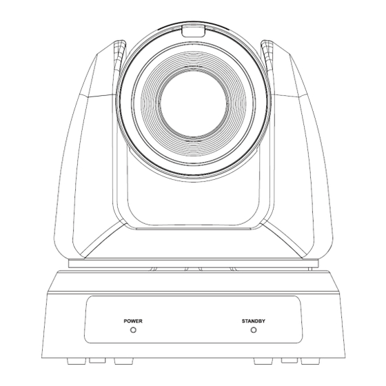
Chapter 2 Function Introduction 2.1 Product I/O functions Item Descriptions Camera lens HD camera lens Displaying the Tally Lamp status of the Tally Lamp camera Power/Standby Displaying the status of the camera, 2.2 LED indicator LED indicator please refer to Item Descriptions Lock... -
Page 5: Leded Indicator
2.2 LED indicator Status Power Standby Startup in progress Green Orange (initialization) In use Green No indicator In standby mode No indicator Orange 2.3 Tally Lamp The Tally lamp function may be enabled through the RS232 command. Please refer to RS-232 command set document... -
Page 6: Chapter 3 Installation
Chapter 3 Installation 3.1 Preparation before installation Installation and connection of HD camera requires special skills. To install by yourself, please follow necessary steps, ensure steady and tight installation of the device, and pay attention to your safety to avoid any accident. 3.1.1 Ensure the safety of the installation environment. - Page 7 Camera 1.5m↑ The Camera (including metal plates) is weighed at about 2.5 kg. If it is to be installed on the ceiling, please use the hanger that has obtained UL security approval to prevent the machine from falling down. ...
- Page 8 2. Lock the metal plate B on ceiling mounted hanger ※Caution: Please use the hanger that has obtained UL security approval Please reserve the hole for the connecting wires of the camera 3. Combine the metal plate A and the metal plate B (1) Push the metal plate A up to the ceiling and then to the right to latch the metal plate B (2) And then secure with 2 M3 silver screws and 1 M3 black screw...
-
Page 9: Connecting Devices
3.3 Connecting devices 4.3.1 RS-232/ RS-422 Connection RS-232/ RS-422 port, up to 7 cameras can be connected in a serial connection Pin No. Function Function RS-232 / RS-422 RS-422 RS-422 RS-232 / RS-422 RS-232 RS-232 RS-232 RS-422 RS-422... -
Page 10: Chapter 4 Remote Control And Setting Menu
Chapter 4 Remote Control and Setting Menu 4.1 Remote control Item Description ➊ ➓ Power Switch Power Number 0-9: Click to call the preset ➋ Preset: Appoint an ID (0-9) to save the current position data Preset Reset: Appoint an ID (0-9) to delete the current position data ➌... -
Page 11: Setting Menu
4.2 Setting Menu Press [MENU] on the remote control to enter the setting menu Level Level Level Descriptions Full Auto/ Shutter Pri/ Mode Exposure mode setting Iris Pri/ Manual Exposure Comp. On / Off AE Level The value can be adjusted after Level -5~5 Exposure Comp. - Page 12 Level Level Level Descriptions Adjustable when the white balance Manual Blue 0~128 Manual mode is set to Picture effect OFF/ Neg / B&W Sharpness 0~14 2D NR OFF/ 1/ 2/ 3 OFF/ Low/ Typical/ 3D NR Highest Standard/ LED mode/ Image Mode Brilliant/ Custom Image mode...
- Page 13 Level Level Level Descriptions When activated, PTZ synchronization can be achieved by controlling with the Presets Refer to the Preset speed PTZ Motion Syn) On / Off setting for this feature. The speed may be adjusted automatically due to the difference of PTZ moving range.
- Page 14 Level Level Level Descriptions Press [ENTER] to be in modify mode; select the item to be modified using IP Address 192.168.100.100 the up and down keys, and modify the value using the left and right keys or the numeric keys. Press [ENTER] to be in modify mode;...
- Page 15 Level Level Level Descriptions Set whether the indicator light is linked with RS232 command Normal (Not linked): The indicator light switch and mode shall be set separately. When the indicator light is on and the default mode is off, additional command is required to set the indicator light mode...
- Page 16 Level Level Level Descriptions 1080p/60 1080p/50 1080p/30 1080p/25 Output Mode Choose the output resolution 720p/60 720p/50 720p/30 720p/25 Factory Reset On / Off Resume the factory default setting Status Display the current setting status...
-
Page 17: Chapter 5 Network Function
Chapter 5 Network Function 5.1 Connecting Camera to Network 5.1.1 Connecting to Internet Two common connection methods are shown below 1. Connecting via switch or router Cat5e cable Cat5e cable Camera Ethernet Switch 器 2. To connect directly through network cable, the IP address of the computer 器... - Page 18 (default IP address) Enter administrator’s account and password 5.2.10 System-User For the first-time login, please refer to to change the default password Lumens IP Camera Username:admin Password:9999(default) 5.1.3 Using RTSP Player to View the Images Free softwares can be used for RTSP connection, such as VLC, Quick Time and...
-
Page 19: Web
5.2 Web Page Function 5.2.1 Live View 9 10 11 Item Descriptions Display camera ID/location Camera ID/ location Please refer to 5.2.5 System - Device Preview window Display the screen currently captured by the camera Enlarge Enlarge the preview image Select the number first and then select [STORE] or [Call]. - Page 20 Live View - Camera Setting 5.2.2 Item Descriptions Mode: Select exposure mode (Full Auto/Shutter Pri/Iris Pri/Manual/) Gain Level: Adjust the gain level (adjustable under the “Manual”) WDR: Set the level of wide dynamic range (WDR) in order to obtain ...
- Page 21 Preset AF: Set whether to perform auto focus after Preset One Push AF: When manual focus mode is on, click this function for one-time autofocus Mirror Mirror: Set image mirroring Flip: Set the mode at which the image is turned ...
- Page 22 Gamma: Gamma Level adjustment; Adjustable when the image mode is set to Custom Brightness: Brightness adjustment of the image; Adjustable when the image mode is set to Custom Saturation: Saturation adjustment of the image; Adjustable when the image mode is set to Custom Sharpness: Sharpness adjustment of the image;...
- Page 23 Audio 5.2.3 Item Descriptions Audio Enable Enable/ Disable Audio Audio In Set MIC In/ Line In Encode Type AAC / G.711 Set Encode sample rate 48 KHz (AAC) 44.1 KHz (AAC) Encode sample rate 16 KHz (AAC) 16 KHz (G.711) ...
- Page 24 Stream 5.2.4 Item Descriptions Stream Support MPEG-TS / RTMP/RTMPS / RTSP / SRT Type Enable Multicast It is suggested to enable Multicast when the number of users online watching the live image simultaneously is more than 4 Require Password Authentication ...
- Page 25 Port 3702, 5353, 8080, 8554, 8556, 8557, 52380, 52381 are used by the camera, please do not set these ports. 5.2.4.1 Streaming Parameter Setting Stream 1: Please refer to for relevant settings RTMP/ RTMPS Copy the URL provided by the RTMP service platform and paste it here to publish ...
- Page 26 5.2.4.1 Streaming parameter setting Function Stream 1 Stream 2 Encode Format H.265 H.264 Resolution 1080P / 720P 720P Frame Rate Setting according to the supported resolution Range 2,000~20,000 2,000~20,000 Bit rate Factory Default 7,000 3,000 Rate Control CBR / VBR IP Ratio Setting according to the supported resolution System - Device...
- Page 27 System - Output 5.2.6 項目 功能說明 Set the output resolution Resolution After switching the resolution, the camera will restart. Please refresh the browser Select YUV422/ YUV420/ RGB HDMI format YUV420 is applicable for 3840x2160 59.94/ 50. Enable/ Disable Privacy Mode After the function is enabled, when the camera is turned off via the Privacy Mode remote control or software, the lens will automatically turn to the...
- Page 28 System - Network 5.2.7 Item Descriptions Network setting of camera. Change of setting is available when DHCP DHCP function is closed HTTP port Set HTTP port. The default Port value is 80 HTTPS port Set HTTPS port. The default Port value is 81 When enabled, PTZ position information can be fed back when the Tracking Data...
- Page 29 5.2.8 System - Security Descriptions Enable/Disable 802.1x Protocol. Setting can be made after enabling. In order to enable this function, the router must support 802.1x Protocol.
- Page 30 System – Date & Time 5.2.9 Descriptions Display the date and time of the camera, set synchronization methods or manually set the date and time.
- Page 31 System - Control 5.2.10 Descriptions Add/ Modify/ Delete user account Supporting 4 - 32 characters for user name and password Please mix uppercase and lowercase letters or numbers for characters. Special symbols or the underlined cannot be used ...
- Page 32 System - Control 5.2.11 Item Descriptions Control Port RS-232/ RS-422 Baud Rate Choose the transmission speed of the control signal as 9600/38400 Protocol VISCA protocol is supported VISCA address The camera ID address 0 ~ 7 can be assigned Tally Lamp Enable/Disable Tally Lamp Set whether the [Tally lamp] is linked with RS232 [Tally Mode] command...
- Page 33 Maintenance 5.2.12 Item Descriptions Select the firmware file, and click [Upgrade] to update the firmware Update takes about 2 - 3 minutes Firmware Update Please do not operate or turn off the device during the update to avoid firmware update failure Factory Reset Reset all configurations to factory default settings The camera setting parameters can be exported and imported/applied to...
- Page 34 Maintenance - Reboot 5.2.13 Item Descriptions Reboot Reboot immediately Disable Disable the reboot settings Set the daily reboot time System - Time Daily reboot Please go to to complete the SNTP server synchronization to set daily reboot Timing Reboot Set the timing reboot time...
- Page 35 About 5.2.14 Descriptions Display the firmware version, serial number, and other related information of the camera. For technical support, please scan the QR code at the bottom right for assistance...
-
Page 36: Chapter 6 Troubleshooting
Chapter 6 Troubleshooting This chapter describes problems you may encounter while using the camera. If you have questions, please refer to related chapters and follow all the suggested solutions. If the problem still occurred, please contact your distributor or the service center. Problems Solutions 1. - Page 37 - Streaming setting - Audio setting...
-
Page 38: Chapter 7 Addendum
Chapter 7 Addendum 7.1 Camera Size Camera Length x Width x Height: 174 x 181.1 x 197.1mm Weight: 1.9Kg (without mental plates) Maximum Rotation Size ... - Page 39 Metal Plate size diagram (1)Metal plate A - camera side Metal plate A locking screw Metal plate A - Camera side...
- Page 40 (2)Metal plate B - ceiling side Metal plate B locking bolt Metal plate B locking screw 3 threaded hole M3 threaded hole M3 threaded hole Metal plate B - ceiling side...
-
Page 41: Chapter 8 Safety Instructions
Safety Instructions Chapter 8 Always follow these safety instructions when using the product: 1 Operation Please use the product in the recommended operating environment, away from water or source of heat. Do not place the product in tilted position or unstable trolley, stand or table. Please clean the dust on the power plug prior to usage. - Page 42 the FCC Rules. These limits are designed to provide reasonable protection against harmful interference when the equipment is operated in a commercial environment. Notice: The changes or modifications not expressly approved by the party responsible for compliance could void the user’s authority to operate the equipment.
-
Page 43: Copyright Information
Lumens is a trademark that is currently being registered by Lumens Digital Optics Inc. Copying, reproducing or transmitting this file is not allowed if a license is not provided by Lumens Digital Optics Inc. unless copying this file is for the purpose of backup after purchasing this product.
Need help?
Do you have a question about the VC-A53 and is the answer not in the manual?
Questions and answers