
Related Manuals for Moxa Technologies EXPC-F2000W


Summary of Contents for Moxa Technologies EXPC-F2000W
- Page 1 EXPC-F2000W Panel Computer Hardware User Manual Version 1.0, January 2024 www.moxa.com/products © 2024 Moxa Inc. All rights reserved.
- Page 2 EXPC-F2000W Panel Computer Hardware User Manual The software described in this manual is furnished under a license agreement and may be used only in accordance with the terms of that agreement. Copyright Notice © 2024 Moxa Inc. All rights reserved.
-
Page 3: Table Of Contents
Bottom View ..........................8 Dimensions ............................9 Touch Panel Buttons and LEDs ......................10 Hardware Connection Description ...................... 12 Installing the EXPC-F2000W Panel Computers ..................12 Notes on Installing and Mounting ....................12 Panel Mounting ..........................13 VESA Mounting (optional) ......................15 Wiring Requirements .......................... - Page 4 Exit Settings ............................44 Exit Saving Changes ........................44 Save Change Without Exit ......................44 Exit Discarding Changes ........................ 44 Load Optimal Defaults ........................44 Load Custom Defaults ........................44 Save Custom Defaults ........................45 Discard Changes .......................... 45 AMT ..............................45 Enabling AMT ..........................
-
Page 5: Introduction
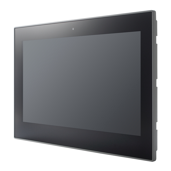
They are also provided with a DisplayPort and VGA video outputs, enabling the extension of the display. The EXPC-F2000W panel computers come in a fanless design for operations in the -40 to 70°C temperature range and a streamlined enclosure for efficient heat dissipation, making them the most reliable industrial platforms available for harsh, hot, outdoor environments such as oil and gas fields, drilling platforms, and power stations, as well as smart heater solutions. -
Page 6: Hardware Specifications
Hardware Specifications NOTE The latest specifications for Moxa’s products can be found at https://moxa.com. Hardware Block Diagram EXPC-F2000W Panel Computer Hardware User Manual... -
Page 7: Hardware Introduction
2. Hardware Introduction The EXPC-F2000W computer is compact, well-designed, and ruggedized for industrial applications. The intelligent OSD display control buttons allow you to indicate control buttons easily in low light environment and identify system hardware failure easily. Multiple serial ports allow you to connect different devices for data operation, and the reliable and stable hardware platform lets you devote your attention to developing your applications. -
Page 8: Bottom View
EXPC-F2150W Series Bottom View AC Models EXPC-F2000W Panel Computer Hardware User Manual... -
Page 9: Dimensions
DC Models Dimensions EXPC-F2120W Series EXPC-F2000W Panel Computer Hardware User Manual... -
Page 10: Touch Panel Buttons And Leds
When the system is in S0 state, press the button for 6 • seconds to force a hard shutdown of the system When the system is in S5 state, press the button for 1 • second to power on the system EXPC-F2000W Panel Computer Hardware User Manual... - Page 11 When an LED is configured for a LAN port, its color indicates the following: Green: 100M speed Yellow: 1GB speed When an LED is configured for a serial port, its color indicates the following: Green: TX Yellow: RX EXPC-F2000W Panel Computer Hardware User Manual...
-
Page 12: Hardware Connection Description
Installing the EXPC-F2000W Panel Computers Notes on Installing and Mounting Before installing and mounting the EXPC-F2000W panel computer, please read the following notes: The EXPC-F2000W panel computer is designed for various installation/mounting methods such wall mounting and VESA mounting. Refer to the relevant mechanical drawings in the following sections before attempting to mount the panel computer. -
Page 13: Panel Mounting
Panel Mounting A panel-mounting kit is included in the package of the EXPC-F2000W panel computers, which includes 10 mounting clamps for EXPC-F2120W Series and 13 mounting clamps for EXPC-F2150W Series. The panel-mounting kit enables installation onto a wall (where space has been cut out to accommodate the rest of the hardware) or on to computing stations where a flush mount is desired. - Page 14 Use short M4 SUS stainless-steel screws (included in the panel-mounting kit) to fasten the clamp arms to the EXPC-F2000W mounting slots, as shown in the diagram below. Use the clamps to fasten the computer to its mounting point. The torque value should not exceed 5 kgf.
-
Page 15: Vesa Mounting (Optional)
VESA Mounting (optional) You can use an optional VESA mounting kit to install the EXPC-F2000W. Eight screws are required to fasten the VESA mounting bracket and must be purchased separately. Refer to the following figures for the VESA mounting dimensions for the EXPC-F2000W panel computers. Attach the bracket on the rear of the... -
Page 16: Grounding
ATTENTION Safety First! Be sure to disconnect the power cord before installing and/or wiring your EXPC-F2000W panel computer. Wiring Caution! Calculate the maximum possible current in each power wire and common wire. Observe all electrical codes dictating the maximum current allowable for each wire size. -
Page 17: Powering On/Off The Expc-F2000W
9 to 36 VDC, 11 A (min.), an ambient temperature of 70 degrees C minimum for DC power construction of EXPC-F2000W series. If you are using a Class I adapter, the power cord should be connected to an outlet with an earthing connection. -
Page 18: Touch Panel Buttons And Leds
For a secure installation, we recommend using a C15 plug with the following dimensions: Touch Panel Buttons and LEDS The EXPC-F2000W panel computer comes with three OSD control buttons and three LED indicators located on the front panel as indicated in the illustration. These intelligent controls will light up when you move your hand over their location. -
Page 19: Extending The Displays
These two LED indicators are programmable; users may use them with their requirements. Extending the Displays The EXPC-F2000W comes with both standard VGA (DB15) and interfaces on DisplayPort the bottom surface. They may be used simultaneously to extend the display across two monitors. See the following figures and tables for the location and pin assignments for the display outputs. -
Page 20: Connecting Data Transmission Cables
This section describes how to connect the EXPC-F2000W panel computer to a network, or serial devices. Connecting to a Network Plug an Ethernet cable into the EXPC-F2000W’s Ethernet port. The other end of the cable should be plugged into your Ethernet network. When the cable is properly connected, the LEDs on the panel computer’s Ethernet port will glow to indicate a valid connection. -
Page 21: Connecting To A Serial Device
Connecting to a Serial Device Use a serial cable to plug your serial device into the EXPC-F2000W’s serial ports. These ports have male DB9 connectors and can be configured for RS-232, RS-422, or RS-485 communication by software. See the following figure for the location of the serial ports. -
Page 22: Connecting To Usb Devices
Connecting to USB Devices The EXPC-F2000W comes with 2 USB 2.0 ports and 2 USB 3.0 ports with type A on the computer. The ports can be used for an external flash disk or hard drive for data storage expansion. You can also use these USB ports to connect to a keyboard or a mouse. -
Page 23: Installing Additional Storage: Ssd
Installing Additional Storage: SSD The EXPC-F2000W panel computer comes with 2 storage slots: A CFexpress slot located on the bottom panel for easy installation and maintenance and an M.2 B Key slot (SATA 3.0) located inside the computer, allowing users to install the second storage with an SSD to fit the applications. The SSD should be of type M.2 2242 B-M. - Page 24 If the SSD has already been installed, remove the screw on the end, and remove the SSD. Insert an SSD card into the socket or replace the existing one. Fasten the SSD card in place and secure it by fastening the screw on the socket. EXPC-F2000W Panel Computer Hardware User Manual...
-
Page 25: Installing A Cfexpress Card
Installing a CFexpress Card The EXPC-F2000W has one CFexpress slot with a PCIe 3.0 interface. Users install a standard CFexpress card using a push-push mechanism. For a list of compatible CFexpress cards contact Moxa technical support team. To install a CFexpress card, do the following: Loosen the screws on the CFexpress slot cover. -
Page 26: Real-Time Clock
Moxa support engineer. If you need to change the battery, contact the Moxa RMA service team at http://www.moxa.com/rma/about_rma.aspx. ATTENTION There is a risk of explosion if the clock’s lithium battery is replaced with an incompatible battery. EXPC-F2000W Panel Computer Hardware User Manual... -
Page 27: Bios Setup
Setup Utility: Enter the BIOS configuration menu • Intel® Management Engine BIOS Extension: Enter the AMT configuration menu (not supported in • models with Intel® Celeron® and Core™ i3 processors) Select F2 to enter the BIOS configuration. EXPC-F2000W Panel Computer Hardware User Manual... - Page 28 Select or go to Submenu. EN TER The BIOS configuration screen will be shown when you enter the Setup Utility option. NOTE The Processor Type information may vary depending on the model that you have purchased. EXPC-F2000W Panel Computer Hardware User Manual...
-
Page 29: Main Page
Main Page The Main page displays basic hardware information, such as model name, BIOS version, and CPU type. Advanced Settings Select the Advanced tab in the main menu to open the advanced features screen. EXPC-F2000W Panel Computer Hardware User Manual... -
Page 30: Boot Configuration
Boot Configuration The Numlock option allows configuration of the Numlock value. Options: On (default), Off. SATA Configuration These items allow you to select the SATA speed limit and enable or disable the RAID mode. EXPC-F2000W Panel Computer Hardware User Manual... -
Page 31: Cpu Configuration
This item indicates the number of cores to enable in each processor package. Hyper-Threading This feature makes the processor resources work more efficiently, enabling multiple threads to run on each core. It also increases processor throughput, improving overall performance on threaded software. Options: Disabled, Enabled (default) EXPC-F2000W Panel Computer Hardware User Manual... -
Page 32: Video Configuration
DVMT Total Gfx Mem. This item allows you to configure the maximum amount of memory DVMT will use when allocating additional memory for the internal graphics device. Options: 256 MB (default), 128 MB, Max. EXPC-F2000W Panel Computer Hardware User Manual... -
Page 33: Chipset Configuration
Touch keypad is enabled by default. When it is in the disabled status, the keypad buttons cannot be operated by the touch keypad. NOTE If keypad is set to be disabled, users need to use a mouse/keyboard to enable it again via the BIOS or a utility. EXPC-F2000W Panel Computer Hardware User Manual... - Page 34 8 minutes, the EXPC-F2150W computer will boot up normally no more than 14 minutes. NOTE When the heater is enabled to heat up the LCM, the function button of the white LED will blink. EXPC-F2000W Panel Computer Hardware User Manual...
- Page 35 When configured as a LAN port, Green light means a transmission speed of 100 Mbps and Yellow light means 1 Gbps speed. When configured as a Serial port, Green light refers to TX and Yellow light refers to PCH-FW Configuration This item allows you to configure the PCH-FW settings. EXPC-F2000W Panel Computer Hardware User Manual...
-
Page 36: Console Redirection
Console Redirection When the Console Redirection Function is enabled, the console information will be output to both the display monitor and through the serial port. Options: Disabled (default), Enabled EXPC-F2000W Panel Computer Hardware User Manual... -
Page 37: Sio Ite8786E
SIO ITE8786E This section allows users to configure SIO settings. Hardware Monitor This item allows you to view stats such as CPU and system temperature, voltage levels, and other chipset information. EXPC-F2000W Panel Computer Hardware User Manual... -
Page 38: Security Settings
This item shows if the system has TMP device and its type. TPM State This item allows you view the status of current TPM settings. Clear TPM This item allows users to remove all TPM context associated with a specific owner. EXPC-F2000W Panel Computer Hardware User Manual... -
Page 39: Set Supervisor Password
To delete the password, select the Set Supervisor Password option and enter the old password; leave the new password fields blank, and then press enter. After setting the supervisor password, users can choose when the input password screen should be displayed. EXPC-F2000W Panel Computer Hardware User Manual... -
Page 40: Power Settings
Disable: System will ask for the password to go to the setup utility Config-Only: System will only ask for the password when you select the config (F2) option Power Settings The section allows users to configure power settings. EXPC-F2000W Panel Computer Hardware User Manual... -
Page 41: Wake On Lan
This item allows you to control the default power of the M.2 B Key slot for 5G module (USB 3.0 interface). Options: Off (default), on M.2 E Key Power This item allows you to control the default power of the M.2 E Key slot for Wi-Fi module (PCIe x1 interface). Options: Off, On (default) EXPC-F2000W Panel Computer Hardware User Manual... -
Page 42: Boot Settings
PXE Booting is booting a system over a network. This item allows users to start PXE over IPv4 or IPv6 Options: Disabled (default), UEFI: IPv4, UEFI: IPv6, UEFI: IPv4/IPv6 USB Boot Set booting to USB boot devices capability. Options: Enabled (Default), Disabled EXPC-F2000W Panel Computer Hardware User Manual... -
Page 43: Timeout
This item allows users to set the number of seconds that the firmware will wait before booting using the original default boot selection. This item allows users to select the boot order. Use F5 (move down) or F6 (move up) to change the value. EXPC-F2000W Panel Computer Hardware User Manual... -
Page 44: Exit Settings
This item allows you to revert to the factory default BIOS values. Options: Yes (default), No Load Custom Defaults This item allows you to load custom default values for the BIOS settings. Options: Yes (default), No EXPC-F2000W Panel Computer Hardware User Manual... -
Page 45: Save Custom Defaults
To enter the BIOS setup utility, press the “F2” key while the system is booting up. The main BIOS Setup screen will appear. Five options will be available: Select Intel® Management Engine BIOS Extension to enter the AMT configuration. EXPC-F2000W Panel Computer Hardware User Manual... - Page 46 Press <Enter> to start the login procedure. Type the default password: admin EXPC-F2000W Panel Computer Hardware User Manual...
- Page 47 Type the new password. It must include both upper-case and lower-case characters, numbers, and special symbols. E.g., Admin’12. Select Intel® AMT Configuration to enable remote access without a local user present for consent, select User Consent, and then select User Opt-in and change the value to None. EXPC-F2000W Panel Computer Hardware User Manual...
- Page 48 Set static IP or DHCP by request. Set Activate Network Access to enable remote access capability. EXPC-F2000W Panel Computer Hardware User Manual...
-
Page 49: Using Amt
The AMT logon screen will appear. Click Log On and type the username (admin) and password. NOTE The AMT port is LAN1. NOTE For details, refer to the Intel AMT Implementation and Reference Guide at: https://software.intel.com/sites/manageability/AMT_Implementation_and_Reference_Guide/default.htm?t url=WordDocuments%2Faccessingintelamtviathewebuiinterface.htm EXPC-F2000W Panel Computer Hardware User Manual... -
Page 50: Administering Secure Boot
Secure Boot helps computers resist attacks and infection from malware. The feature defines an interface between the operating system and BIOS. It detects tampering with boot loaders, key operation system files, and unauthorized option ROMs by validating their digital signatures. EXPC-F2000W Panel Computer Hardware User Manual... -
Page 51: Enabling Uefi Secure Boot
Set as “enabled” in “Restore Secure Boot to Factory Settings” under Administer Secure Boot menu. Press F10 as save and exist. The Microsoft key is included in the BIOS by default. If you cannot boot up using a non-Windows OS, use the following example. Enroll EFI Image EXPC-F2000W Panel Computer Hardware User Manual... -
Page 52: Enroll Customer Key
Enter “Administer Secure Boot” once again and see “Select a UEFI file as trusted for execution”, put loader into the database named and followed by the UEFI standard \EFI\BOOT\BOOT{machine type short-name}. E.g., efi\boot\BootX64.efi, Debian (EFI\debian\grubx64.efi), Suse (EFI\opensuse\grubx64.efi) Enroll Customer Key EXPC-F2000W Panel Computer Hardware User Manual... - Page 53 Enter “DB OPTION” and enroll your key. Please make sure your key is CRT format and uses RSA 2048 or better. EXPC-F2000W Panel Computer Hardware User Manual...
-
Page 54: Upgrading The Bios
Before upgrading the BIOS, you must create a bootable USB drive as a system boot device for use in the future. Insert a USB disk in the computer’s USB drive. Search for “format” and select Create and format hard disk partitions. EXPC-F2000W Panel Computer Hardware User Manual... -
Page 55: Step 2: Prepare The Upgrade File
You must use the BIOS upgrade installation file to upgrade the BIOS. Contact Moxa’s technical department for assistance. The BIOS upgrade file includes an efi folder and an xxxx.efi file. Copy the efi folder and xxxx.efi file to the bootable USB disk. EXPC-F2000W Panel Computer Hardware User Manual... -
Page 56: Step 3: Run The Upgrade Program On Your Computer
Moxa). Wait until the upgrade procedure is completed. NOTE Do NOT switch off the power supply during the BIOS upgrade, since doing so may cause the system to crash. EXPC-F2000W Panel Computer Hardware User Manual... - Page 57 If the system has more than one boot device, you will see more than one fsx (x represents the number). Go to each fsx (x stands for the number) and type ls to view the content of the boot device. If you find an upgrade file, run it. EXPC-F2000W Panel Computer Hardware User Manual...
-
Page 58: Configuring The Serial Interface
5. Configuring the Serial Interface Overview The EXPC-F2000W supports the following serial modes: RS-232, RS-422, 2-wire RS-485, and 4-wire RS-485. These modes can be configured on COM3, COM4, and COM5 (COM1, COM2, and COM3 on the device label). Installing the SerialInterface Utility Complete the following steps to install the SerialInterface utility: The SerialInterface setup *.exe file can be found on the product DVD: <Software... - Page 59 Click Next to continue. The default destination folder is C:\Program Files\Moxa\Moxa Serial Interface; click Install to continue. Click Finish to complete installation. EXPC-F2000W Panel Computer Hardware User Manual...
-
Page 60: Configuring The Serial Interface Mode
Configuring the Serial Interface Mode Complete the following steps to configure the interface mode: From the Start menu, Click All Programs Moxa Serial Interface -> Moxa Serial Interface. Select a COM port (COM3, COM4, COM5). EXPC-F2000W Panel Computer Hardware User Manual... - Page 61 Select the mode for the port selected in the previous step. Click Apply. EXPC-F2000W Panel Computer Hardware User Manual...
-
Page 62: Regulatory Approval Statement
European Community Warning: This is a Class A product. In a domestic environment this product may cause radio interference, in which case the user may be required to take compensatory measures. EXPC-F2000W Panel Computer Hardware User Manual...
Need help?
Do you have a question about the EXPC-F2000W and is the answer not in the manual?
Questions and answers