
Related Manuals for Keysight U9361C


Summary of Contents for Keysight U9361C
- Page 1 U9361C/F/G/M RCal Receiver Calibrator This manual provides documentation for the U9361C/F/G/M running the Microsoft Windows 10 operating system. MEASUREMENT GUIDE...
- Page 2 Notices DOCUMENT OR ANY INFORMATION commercial computer software or CONTAINED HEREIN. SHOULD commercial computer software KEYSIGHT AND THE USER HAVE A documentation. No additional © Keysight Technologies, Inc. SEPARATE WRITTEN AGREEMENT government requirements beyond 2021- 2023 WITH WARRANTY TERMS those set forth in the EULA shall...
-
Page 3: Table Of Contents
Contents 1 Getting Started Overview Requirements Available RCal Models and Options RCal I/O USB Power & Control External 10 MHz Reference RF Output LED Indicators on RCal Module RCal Software - Configuration Left-Panel Controls Configuration Table Overview RCal Configuration Table – Parameters RCal Software –... - Page 4 Contents 2 Making Measurements Equipment Setup Setting Up a Signal Analyzer to Control a Signal Generator Performing a Simple Magnitude Calibration Compatible Signal Generators: Measuring Magnitude Cal with Multiple States Compatible Signal Generators Using Complex Cal to Improve EVM in a 128 QAM Signal Compatible Signal Generators: Using RCal Data Generated on X-Apps but Used with the 89600 VSA Software...
-
Page 5: Getting Started
Keysight Vector Signal Generator U9361C/F/G/M RCal Receiver Calibrator Measurement Guide Getting Started This section explains how to setup and initialize the Frequency Extender with the Vector Signal Generator. The following topics can be found in this section: “Overview” on page 4 “RCal I/O”... -
Page 6: Overview
— Compact Design: It is palm-sized, USB-powered and controlled, making it easy to use and space efficient. — Precision: It has ultra-stable and repeatable functions, supported with precision factory calibration data. — Comprehensive Corrections: Provides both magnitude and phase corrections, using tunable BPSK comb modulation. U9361C/F/G/M RCal Measurement Guide... -
Page 7: Requirements
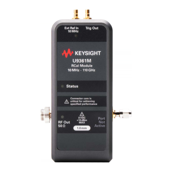
2.4 mm male (option MMM) or 2.4 mm female (option MMF) U9361G 10 MHz - 67 GHz 1.85 mm male (option MMM) or 1.85 mm female (option MMF) U9361M 10 MHz – 110 GHz 1.0 mm male (option MMM) U9361C/F/G/M RCal Measurement Guide... -
Page 8: Rcal I/O
When plugged in, the RCal module will boot up, accompanied by an LED boot sequence. When boot-up is complete, the LEDs will settle to Status = Green. For more information about RCal’s LED codes, see “LED Indicators on RCal Module” on page U9361C/F/G/M RCal Measurement Guide... -
Page 9: External 10 Mhz Reference
Mismatch errors can be reduced with small fixed attenuators, such as a 6 dB attenuator. Higher frequencies require smaller connector geometries, such as 1 mm. To avoid damaging these fragile connectors, please follow the recommendations “Connector Care” on page U9361C/F/G/M RCal Measurement Guide... -
Page 10: Led Indicators On Rcal Module
Green Blink = Busy Amber Blink = Temperature Unstable (during warm-up period) Red = USB Power Failure Red Blink = USB Power Failure Red Blink = External Ref unlocked Red Blink = Processor Error Blue Blink = Self Identification U9361C/F/G/M RCal Measurement Guide... -
Page 11: Rcal Software - Configuration
Input/Output > Calibration > Configuration. If this tab is missing, then the instrument is most likely using an older software revision, missing a license, or is unsupported. (See “Available RCal Models and Options” on page RCal calibrations are created and applied within the calibration configuration window. U9361C/F/G/M RCal Measurement Guide... -
Page 12: Left-Panel Controls
Select Calibrator: Selects the RCal module for use. A single signal analyzer can have multiple RCal modules connected to different ports, but only one module can be used and controlled at a time. The RCal Model and Serial numbers will appear below this tab. U9361C/F/G/M RCal Measurement Guide... -
Page 13: Configuration Table Overview
1. Use Current Meas automatically populates the Cal Row using parameters from the current X-Series Signal Analyzer application. This feature is supported by the Signal Analyzer mode and many others, but it is not supported by every X-Series Signal Analyzer application. U9361C/F/G/M RCal Measurement Guide... -
Page 14: Rcal Configuration Table - Parameters
(Read only) Date and time that last calibration was successfully executed. Applied (Read only) “Yes” if successfully applied, “---“ if not yet calibrated, and “No” if not applied. Ext Mixer (Read only) Applies only if Input = Ext Mixer U9361C/F/G/M RCal Measurement Guide... - Page 15 IF path. (depending on instrument model and options): 10 MHz, 25 MHz, 40 MHz, 85 MHz, 125 MHz, 140 MHz, I60 MHz, 255 MHz, 510 MHz, 1 GHz, 1.5 GHz, 2 GHz, and 4 GHz. U9361C/F/G/M RCal Measurement Guide...
- Page 16 Normal is default for a given band (can be either LO > RF or LO < RF). Alternate if using alternate-side mixing for digital demodulation to flip the side of image products, then you would want to calibrate the alternate mixing side. All does both. U9361C/F/G/M RCal Measurement Guide...
- Page 17 Match State False (default) allows instrument to interpolate and approximate when correction data is “close”; on page 19 for more details. reduces frequency of Apply errors. True requires strict match between correction data and instrument settings. U9361C/F/G/M RCal Measurement Guide...
-
Page 18: Rcal Software - Calibration And Application
— The signal analyzer reads relevant factory calibration data from the RCal module to prepare for corrections. — The signal analyzer makes measurements and calculates the difference between expected and actual measurements. — The differences are stored as corrections to be applied to a later measurement. U9361C/F/G/M RCal Measurement Guide... -
Page 19: Applying A Calibration
Match State rules. The Applied column should now show Yes, indicating that the selected calibration is being applied. When calibrations are active, the Corr CCorr (Complex Correction) option on the measurement panel should show "RCal" in orange as shown below. U9361C/F/G/M RCal Measurement Guide... -
Page 20: Errors, Warnings, And Status
— Change settings from Auto to Man (manual), to prevent automatic or coupled changes to parameters. — Expand the range of RCal, and/or add RCal rows, to include the state or path that caused the mismatch, and recalibrate. U9361C/F/G/M RCal Measurement Guide... -
Page 21: Best Rcal Configuration Practices
False. When the Match State is set to False, the following rules are followed: — Situations that are close enough will use the closest available correction. — Situations that are too different will never be selected even when the Match State is set to False. U9361C/F/G/M RCal Measurement Guide... -
Page 22: Multiple Rows, Overlap, And Dual Corrections
When performing a calibration, no corrections will be made outside of the calibration bandwidth. However, if performing a calibration on a signal with a wider bandwidth than the calibration bandwidth, corrections will still be applied within the calibrated bandwidth. U9361C/F/G/M RCal Measurement Guide... -
Page 23: Key Steps For Every Rcal Calibration
— Make sure that the Ext 10 MHz reference is connected and that the selected USB connection supplies ample current. — If source control is desired for the calibration, connect the necessary input and output triggers between the analyzer and source. U9361C/F/G/M RCal Measurement Guide... -
Page 24: Connector Care
8. Torque the cable or device to the final value using a torque wrench. Cleaning Connectors 1. Inspect the connectors for dust, dirt, metal fragment, oils or film, and debris. 2. Blow off any dust with a filtered, clean supply of compressed air. U9361C/F/G/M RCal Measurement Guide... -
Page 25: Visual Inspection
(do not apply alcohol directly to the parts). When using isopropyl alcohol to clean connectors do not allow the liquid to flow down Keysight U9361 RCal Receiver Calibrator inside the connector. This may cause measurement errors due to residue inside the connector. - Page 26 Getting Started Connector Care U9361C/F/G/M RCal Measurement Guide...
-
Page 27: Making Measurements
Keysight Vector Signal Generator U9361C/F/G/M RCal Receiver Calibrator Measurement Guide 2 Making Measurements The following topics can be found in this section: — “Equipment Setup” on page 26 — “Performing a Simple Magnitude Calibration” on page 29 — “Measuring Magnitude Cal with Multiple States” on page 34 —... -
Page 28: Equipment Setup
— The Trig connections between the signal generator and signal analyzer are recommended for demos involving source control. The software trigger SW trigger) can also be used without a physical connection. For the measurement examples below, we will be using the SW trigger. U9361C/F/G/M RCal Measurement Guide... - Page 29 Making Measurements Equipment Setup — The USB-C connector is located in front of the Ext Ref In and Trig Out ports, as shown below. U9361C/F/G/M RCal Measurement Guide...
-
Page 30: Setting Up A Signal Analyzer To Control A Signal Generator
2. On the Signal Analyzer in Spectrum Analyzer mode, select Meas Setup > Source tab > Select Source. 3. Enter either the GPIB or LAN source address and then select Add Specified Address. In the Available Source List, highlight the address, and then choose Select Highlighted Source. U9361C/F/G/M RCal Measurement Guide... -
Page 31: Performing A Simple Magnitude Calibration
Stop to 4 GHz. 6. Set # Points > 101. 7. Select More > Step Dwell > 2.00 msec. 8. Set RF Out > On. The RF output state is indicated by the LED next to the toggle button. U9361C/F/G/M RCal Measurement Guide... - Page 32 4. Select Sweep > Sweep Config tab and set the Points to 101. 5. Select Trace. In the Select Trace drop down, select Trace 1. 6. Set Trace Type to Max Hold, and then in the View/Blank area, select Active. U9361C/F/G/M RCal Measurement Guide...
- Page 33 The trace will begin to flatten as the maximum points are saved. 7. Once the trace has stabilized, save it for comparison by selecting View in the View/Blank area. 8. Disconnect the RF cable from the signal generator and connect it to the RCal module. U9361C/F/G/M RCal Measurement Guide...
- Page 34 10. Select Use Current Meas, then select the Calibrate checkbox > Calibrate Checked Rows to populate a row using the current measurement settings, and run the calibration. 11. When the calibration is complete, select Apply, then Close the window. U9361C/F/G/M RCal Measurement Guide...
- Page 35 14. Set Trace Type to Max Hold, and then in the View/Blank area, select Active. The trace will begin to flatten as the maximum points are saved. Notice the improvement in the measurement. U9361C/F/G/M RCal Measurement Guide...
-
Page 36: Measuring Magnitude Cal With Multiple States
On the Signal Analyzer 1. Connect the RF output of the signal generator to the RF input of the signal analyzer. 2. Select Mode > Spectrum Analyzer > Mode Preset to set the signal analyzer to a known state. U9361C/F/G/M RCal Measurement Guide... - Page 37 3. Select FREQ and set Start Freq to 24 GHz and Stop Freq to 25 GHz. 4. Select Sweep > Sweep Config tab > Points > 101. 5. Select Meas Setup> Source tab > Source Setup Table > Point Trigger to SW Trigger. U9361C/F/G/M RCal Measurement Guide...
- Page 38 View/Blank to View. 10. Select Meas Setup > Source tab> RF Output > Off to disable the RF output on the signal generator. 11. Disconnect the cable from the signal generator and connect it to the RCal module. U9361C/F/G/M RCal Measurement Guide...
- Page 39 12. On the signal analyzer, select Input Output > Calibration tab > Configuration to open the Calibration Configuration window. 13. Select Use Current Meas > Calibrate checkbox to select > Calibrate Checked Rows to populate a row using the current measurement settings and then run the calibration. U9361C/F/G/M RCal Measurement Guide...
- Page 40 17. Verify the calibration by adding another trace. Navigate to Trace > Select Trace > Trace 2 Set Trace Type to Max Hold and set View to Active Wait for the trace to stabilize, then select View > View to store the trace. U9361C/F/G/M RCal Measurement Guide...
- Page 41 19. Select Meas Setup > Source > RF Output > Off. 20. Disconnect the cable from the signal generator and connect it to the RCal module. 21. Select Input Output > Calibration tab > Configuration. 22. Select Row 1 > Duplicate Row. U9361C/F/G/M RCal Measurement Guide...
- Page 42 Trace > Select Trace > Trace 3 Trace Type to Max Hold View to Active Observe the differences between the uncorrected trace (Trace 1), the corrected trace (Trace 2), and the corrected trace with Preselector Bypass enabled (Trace 3). U9361C/F/G/M RCal Measurement Guide...
- Page 43 Making Measurements Measuring Magnitude Cal with Multiple States U9361C/F/G/M RCal Measurement Guide...
-
Page 44: Using Complex Cal To Improve Evm In A 128 Qam Signal
If accessing the instrument via a Remote Desktop connection, select the Screen tab (at the top left of the display) to open the Mode/Measurement/View Selector window. 2. Select Preset > Mode Preset to set the analyzer to a known state. U9361C/F/G/M RCal Measurement Guide... - Page 45 9. On the signal generator, select RF Output > Off to disable the RF output. 10. Disconnect the cable from the signal generator and connect it to the RCal module. 11. Select Input/Output > Calibration tab > Configuration to navigate to the Calibration Configuration window. U9361C/F/G/M RCal Measurement Guide...
- Page 46 Mech Atten: Step Mech Atten Start: 10 dB Mech Atten Stop: 10 dB Elec Atten: Bypass IF Gain: Auto IF Path: 25 MHz Preamp: Off Phase Noise Opt: Best Wide Offset uW Path Ctrl: uW Presel Bypass U9361C/F/G/M RCal Measurement Guide...
- Page 47 13. Select the Calibrate checkbox for Row 1 and then Calibrate Checked Rows > OK. 14. When calibration is complete, select Apply. 15. Disconnect the cable from the RCal module and connect it to the signal generator. 16. Select RF Output > On. U9361C/F/G/M RCal Measurement Guide...
- Page 48 Path). This is an easy way to add the effects of additional loss into the system, instead of adding another element like an attenuator, external filter, and so on. Another state must be added in order to properly apply corrections to both RF paths. U9361C/F/G/M RCal Measurement Guide...
- Page 49 22. Disconnect the cable from the RCal module and connect it to the signal generator. 23. On the signal generator, select RF Output > On. The EVM is now reduced with the Standard path. By leaving both paths applied, the instrument will automatically select the proper calibration state. U9361C/F/G/M RCal Measurement Guide...
-
Page 50: Using Rcal Data Generated On X-Apps But Used With The 89600 Vsa Software
1. Select Mode/Measure > Launch VSA to start the VSA application. 2. Set Center Frequency to 5 GHz and Span to 20 MHz. Select the Auto-range icon to bring the signal up on the display. 3. Select Window > Trace Layout > Grid 2x2. U9361C/F/G/M RCal Measurement Guide... - Page 51 4. Select Meas Setup > Measurement Type > General Purpose > Digital Demod. 5. Select Meas Setup > Digital Demod Properties. 6. Configure the following measurement parameters under the Format tab. Format: 128-QAM Symbol Rate: 10 MHz Points/Symbol: 10 U9361C/F/G/M RCal Measurement Guide...
- Page 52 Using RCal Data Generated on X-Apps but Used with the 89600 VSA Software Result Length: 501 Symbols 7. Under the Filter tab, set the following matched filter parameters. Measurement Filter > Root Raised Cosine Reference Filter > Raised Cosine U9361C/F/G/M RCal Measurement Guide...
- Page 53 Making Measurements Using RCal Data Generated on X-Apps but Used with the 89600 VSA Software Alpha/BT: (rolloff) > 0.5 8. Select Input > Extensions and set IF Path to 25 MHz. U9361C/F/G/M RCal Measurement Guide...
- Page 54 9. Under the same Extensions window, scroll down and enable RCal Corrections and select RCal Correction > Correction. 10. Perform an Auto-range by selecting the icon. 11. Exit the input window. EVM should now be improved. For this example, EVM went from 1.02% to 0.188%. U9361C/F/G/M RCal Measurement Guide...
-
Page 55: Using Rcal As A Cw Source And Comb Generator
— Comb Spacing: Select the spacing of the frequency comb when using a comb signal The table below gives minimum and maximum frequency and comb spacing options when using Calibrator Control: Minimum Maximum Frequency 10 MHz 110 GHz Comb Spacing 100 kHz 1.344 GHz U9361C/F/G/M RCal Measurement Guide... -
Page 56: Example Calibrator Control Outputs
Making Measurements Using RCal as a CW Source and Comb Generator Example Calibrator Control Outputs: CW signal at 10 GHz. The amplitude of the signal can be adjusted using external attenuation. U9361C/F/G/M RCal Measurement Guide... - Page 57 Making Measurements Using RCal as a CW Source and Comb Generator Comb signal centered at 10 GHz with 500 MHz spacing. Comb signal centered at 10 GHz with 100 MHz spacing. U9361C/F/G/M RCal Measurement Guide...
-
Page 58: Using Rcal Directly From The 89600 Vsa
Using RCal Directly from the 89600 VSA In the latest 89600 VSA 2024 Patch Release, integration with the RCal U9361 receiver calibrator is possible with any Keysight hardware that communicates with the VSA, including oscilloscopes, digitizers and signal analyzers. Making it possible to perform a comprehensive receiver system calibration right up to the DUT reference plane. -
Page 59: Compatible Signal Generators
To integrate the U9361 RCal with the 89600 VSA, you will need the 89601200C license on the same PC where the VSA software is installed. 1. Open Keysight Connection Expert and add an instance of the RCal U9361 Receiver Calibration to the Keysight IO Library as a USB instrument referenced in the VISA address. - Page 60 Using RCal Directly from the 89600 VSA e. In the Select the instrument(s) to use for each logical instrument configuration area, select Keysight Technologies U9361 RCal Receiver Calibrator > OK. Now all RCal units should show up in the bottom window. (Most likely, you will have only one.)
-
Page 61: Performing Receiver Calibration Using Rcal
Making Measurements Using RCal Directly from the 89600 VSA 3. In the Keysight Connection Expert application, select the RCal unit that you added to the Keysight IO Library. Performing Receiver Calibration Using RCal 1. Connect the signal generator RF Output to the signal analyzer RF input. - Page 62 For this example, the amplitude is at -10.93 dBm, indicating approximately 1 dB of signal path loss. 7. Connect the RF Output of the RCal instrument to the RF In on the spectrum analyzer. 8. In the 89600 VSA Utilities menu, select System Calibration. U9361C/F/G/M RCal Measurement Guide...
- Page 63 — Number of Points — Magnitude Flatness Threshold — Phase Linearity Threshold — Calibration File Name, if you want to reuse the coefficients from this calibration at a later time — Setup File Name and more U9361C/F/G/M RCal Measurement Guide...
- Page 64 Leveraging the RCal with the 89600 VSA enables you to calibrate the whole receiver system at the DUT reference plane, as shown below. In this example system, we have a receiver test fixture, downconverter, and Keysight UXR oscilloscope, each with their respective losses as a function of frequency.
-
Page 65: From A Receiver Calibration To A Comprehensive End-To-End Calibration
(DUT). 89600 VSA software with 2024 patch release now can connect with RCal to perform the calibration and U9361C/F/G/M RCal Measurement Guide... - Page 66 Making Measurements Using RCal Directly from the 89600 VSA apply the calibration coefficients with your measurements. You can further use the PWSG AWU software to perform an end-to-end system calibration and get the calibrated source. U9361C/F/G/M RCal Measurement Guide...
-
Page 67: Comparing Amplitude Accuracy Using Rcal Vs. A Power Sensor
If accessing the instrument via a Remote Desktop connection, select the Screen tab (at the top left of the display) to open the Mode/Measurement/View Selector window. 2. Select Mode > Mode Preset to set the analyzer to a known state. U9361C/F/G/M RCal Measurement Guide... - Page 68 Using RCal Directly from the 89600 VSA 3. Connect the RF Input of the signal analyzer to the RF Output of the signal generator. 4. Select Frequency > Start Freq 1 GHz > Stop Freq 20 GHz. U9361C/F/G/M RCal Measurement Guide...
- Page 69 5. Select Sweep > Sweep Config tab > Points 101. 6. Select Meas Setup > Source Setup Table > Point Trigger SW Trigger. 7. Close the Source Setup Table and set Source Mode to Tracking and RF Output to On. U9361C/F/G/M RCal Measurement Guide...
- Page 70 8. On the signal generator select RF > On. 9. Select Trace > and set Trace 1 to Max Hold. 10. Once the trace has stabilized, save it for comparison by selecting View > View. U9361C/F/G/M RCal Measurement Guide...
- Page 71 Using RCal Directly from the 89600 VSA 11. Select Meas Setup > Source > RF Output Off. 12. Disconnect the cable from the signal generator and connect it to the RCal module. 13. Select Input Output > Calibration > Configuration. U9361C/F/G/M RCal Measurement Guide...
- Page 72 Duplicate this row if comparisons for both the Standard Path and Preselector Bypass are desired. 15. Select the Calibrate checkbox on both rows and then Calibrate Checked Rows to run the calibration. 16. When calibration is complete, select Apply. U9361C/F/G/M RCal Measurement Guide...
- Page 73 20. Select Marker 1 and set Marker Mode to Normal and Marker Frequency to 2.5 GHz. Repeat this for Marker 2 through 7 for 5 GHz, 8 GHz, 11 GHz, 14 GHz, 17 GHz, and 20 GHz. U9361C/F/G/M RCal Measurement Guide...
- Page 74 Connection to confirm the device is connected properly. 26. Return to view the power meter measurements, and set FREQ > 2.5 GHz, 5 GHz, 8 GHz, 11 GHz, 14 GHz, 17 GHz, and 20 GHz, recording the measured power at each frequency point. U9361C/F/G/M RCal Measurement Guide...
- Page 75 The average difference in results between the Power Sensor and the measurement using an RCal calibration for this test case was 0.192 dBm across the selected measurement span. 27. Before disconnecting the power sensor, select Return > Return > and set Channel A Off. U9361C/F/G/M RCal Measurement Guide...
-
Page 76: Using Rcal As A Scalar Network Analyzer
3. Select Preset to set the signal analyzer to a known state. 4. Select Frequency > Start Freq 4 GHz > Stop Freq 4.2 GHz. 5. Select Trace > Detector tab > Peak. 6. Select Sweep > Sweep Config tab > Points 201. U9361C/F/G/M RCal Measurement Guide... - Page 77 This will result in the sweep points being space 1 MHz apart. 7. Select Input/Output > Calibrator Control tab > Cal Source to RCal Module 1 > Frequency to 4 GHz. 8. If your RCal unit has Option CPX, ensure Signal is set to CW. U9361C/F/G/M RCal Measurement Guide...
- Page 78 11. Select Input/Output > Calibrator Control > Frequency and scroll the RPG slowly 200 times until the Frequency reads 4.210 GHz. (If you go too fast, you will see steps in the trace.) Alternatively, you can use the right arrow key. U9361C/F/G/M RCal Measurement Guide...
- Page 79 RPG know slowly 200 times until the Frequency reads 4.210 GHz. Alternatively, you can use the right arrow key. This will trace out the frequency response across all 201 points of the RCal plus the attenuator. U9361C/F/G/M RCal Measurement Guide...
- Page 80 Using RCal as a Scalar Network Analyzer 17. Select Trace 2 > View/Blank View. 18. Select Trace > Trace 3 > View/Blank to Active. 19. Select the Math tab > Operand 1 to Trace 2 and Operand 2 to Trace 1. U9361C/F/G/M RCal Measurement Guide...
- Page 81 21. Select Trace > Trace 3 >View/Blank to View. 22. Select Marker > Properties tab > set Relative To Marker 2. U9361C/F/G/M RCal Measurement Guide...
- Page 82 Using RCal as a Scalar Network Analyzer 23. Select Amplitude > Scale/Div to 5 dB. Notice that the marker is approximately 3 dB, the value of the attenuator. 24. Select Input/Output > Calibrator Control > Output Off. U9361C/F/G/M RCal Measurement Guide...
-
Page 83: Programming With Matlab
Keysight Vector Signal Generator U9361C/F/G/M RCal Receiver Calibrator Measurement Guide Programming with MATLAB This section explains how to setup and initialize the Frequency Extender with the Vector Signal Generator. SCPI commands can be used to help simplify and speed up the RCal configuration and calibration process. -
Page 84: Magnitude Calibration And Comparison With Use Current Meas
% Set X-Series Signal Analyzer to basic mode, set trace to <> hold order to see avg. power % level before calibration fprintf(my_SA, ':INST:SEL SA'); fprintf(my_SA, ':SYST:PRES:TYPE MODE'); fprintf(my_SA, ':FREQ:CENT %dGHz', center_freq); fprintf(my_SA, ':FREQ:SPAN %dGHz', freq_span); fprintf(my_SA, ':TRAC1:TYPE MAXH'); U9361C/F/G/M RCal Measurement Guide... - Page 85 ':SYST:CAL:INIT:SEL'); input('Switch cable from RCal to SG after Calibration complete, apply calibrations manually, then press ''enter''...', 's'); fprintf(my_SA, ':SYST:CAL:ROW1:STAT ON'); fprintf(my_SA, ':TRAC2:TYPE MAXH'); input('Press ''Enter'' when trace 2 stabilized...','s'); fprintf(my_SA, ':TRAC2:MODE VIEW'); disp("Magnitude Cal Demo Complete"); U9361C/F/G/M RCal Measurement Guide...
-
Page 86: Calibration Table Setup For Vma
= query(my_SA, ':POW:ATT?') preamp = query(my_SA, ':POW:GAIN:BAND?') preamp_enable = query(my_SA, ':POW:GAIN?') elec_atten = query(my_SA, ':POW:EATT?') coupling = query(my_SA, ':INP:COUP?') uW_path = query(my_SA, ':POW:MW:PATH?') fprintf(my_SA, ':DDEM:IF:GAIN:AUTO ON') IF_gain = query(my_SA, ':DDEM:IF:GAIN:AUTO?') pno = query(my_SA, 'DDEM:FREQ:SYNT?') %Phase Noise Offset U9361C/F/G/M RCal Measurement Guide... - Page 87 % Bypass electronic attenuation if it is disabled or 0dB % QUERY automatically returns ['x' char newline] if elec_atten == ['0' char newline] fprintf(my_SA, ':SYST:CAL:ROW1:EATT:TYPE BYP'); else elec_atten_num = str2num(elec_atten) elec_atten_start = num2str(elec_atten_num - (elec_atten_range/2)) elec_atten_stop = num2str(elec_atten_num + U9361C/F/G/M RCal Measurement Guide...
- Page 88 % Mixing Mode and Match State are default on new row addition % Uncomment below to automatically calibrate for single added row % input('Switch cable from SG to RCal Unit, then press ''enter''...', 's'); % fprintf(my_SA, ':SYST:CAL:INIT:SEL') U9361C/F/G/M RCal Measurement Guide...
- Page 89 This information is subject to change without notice. © Keysight Technologies 2023 Edition 1, November 1, 2023 U9361-90003 www.keysight.com...
Need help?
Do you have a question about the U9361C and is the answer not in the manual?
Questions and answers