Table of Contents
Advertisement
Quick Links
Advertisement
Table of Contents

Related Manuals for ControlByWeb X-432


Summary of Contents for ControlByWeb X-432
-
Page 2: Table Of Contents
2.2.5 Network Connection ............................25 2.3 Establishing Communications for Setup ......................26 2.3.1 Method 1: Assign a Temporary IP address to X-432™ ...................26 2.3.2 Method 2: Assign a Temporary IP Address to the Configuration Computer ............28 Appendix A: Restoring Factory Default Settings ......................143 Appendix B: Installing New Firmware ..........................144... -
Page 3: Trademark And Copyright Information
Trademark and Copyright Information This document is Copyright ©2013-2023 by Xytronix Research & Design, Inc. All rights reserved. X-432™,WebRelay, ControlByWeb™, and Xytronix Research & Design™ are trademarks of Xytronix Research & Design™, Inc. 2005-2023. All other trademarks are the property of their respective owners. -
Page 4: Warranty
X-432™ Users Manual Warranty This Xytronix Research & Design, Inc. product has a warranty against defects in material and workmanship for a period of one year from the date of shipment. During the warranty period, Xytronix Research & Design, Inc. will, at its option, either repair or replace products that prove to be defective. -
Page 5: Fcc Statement
X-432™ Users Manual FCC Statement This device complies with Part 15 of the FCC Rules. Operation is subject to the following two conditions: - This device may not cause harmful interference. - This device must accept any interference received, including interference that may cause undesired operation. -
Page 6: Installation Guidelines (Read Before Installing)
X-432™ does not employ a general purpose computer operating system and does not have features, such as telnet, FTP, SSH, nor uncontrolled open ports. This means it is unlikely for someone to ‘break in’ to X-432™ and access other devices on your local network. The simplicity of X-432™ makes it a inherently secure device. -
Page 7: Section 1: Introduction
IP network including private networks, IP-based industrial control networks, and the Internet. Users can operate the X-432™ using a web browser, or custom applications can be written to control the X-432™ from a computer, PLC, or other automation controller. In addition, custom control scripts can be written and executed using BASIC programming language. -
Page 8: X-432™ Features
Monitor analog inputs. Control relays or trigger email messages based upon the analog reading. Each analog input has a 0 to 5 volt range, and offers 12 bits of resolution. Remote Relays Control relays on other ControlByWeb products. Real-time Clock Manual or NTP capability. -
Page 9: Applications
X-432™ a very powerful, yet simple controller. You can use the X-432™ to control motors, lights, coils, pumps, valves, bells, etc. You can also use it to monitor alarms sensors, switches, fluid level switches, battery voltage, temperature, humidity, and much more. A few... -
Page 10: X-432™ Models Available
(Wall Mount) enclosure Temperature/Humidity Digital temperature and humidity sensor housed in vented X-DTHS-WMX Sensor (Wall Mount) plastic enclosure DIN Rail Mounting Clips Removable mounting clips to attach the X-432 to a DIN rail. DRC-12C Xytronix Research & Design, Inc. Page 10... -
Page 11: Connectors & Indicators
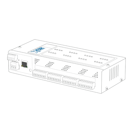
Figure 1.4a - Connections & Indicators I/O Connectors X-432™ has nine 8-position removable screw terminal connectors, one 5-position removable screw terminal connector, one 3-position removable screw terminal connectors and an Ethernet connector. These connectors are used to connect relay contacts, digital inputs, analog inputs, power and network. -
Page 12: Accessing X-432
Standard Access Using a Web Browser X-432™ has a built-in web server that provides simple web pages that can be accessed directly using a standard web browser. This allows users to access the unit with NO SPECIAL SOFTWARE installed on their computer. -
Page 13: Section 2: Installation And Setup
2.1 Mounting X-432™ can sit on a shelf or be mounted to a wall or DIN Rail (35mm by 7.55mm). It should be mounted in a clean, dry location where it is protected from the elements. Ventilation is recommend for installations where ambient air temperatures are expected to be high See Appendix J: Mechanical Information for additional mechanical details. -
Page 14: Din-Rail Mounting
2.1.3 DIN-Rail Mounting Attach a wall mount bracket (shown above) to the side of the X-432™ by using two #6 screws. Attach the DIN- Rail mounting clips [Part number DRC-12C sold separately] to the wall mount bracket by using two additional #6 screws (pictured below). -
Page 15: Connection
4. Apply power. It is recommended that the load (device to be controlled) not be connected to the X-432™ until after the X-432™ has been configured and tested. By doing this, wiring and configuration mistakes will not cause the load device to turn on unexpectedly. -
Page 16: Power Supply Connection
Egnd ground. X-432™ requires power for its internal logic circuits. Connect a 9-28 VDC power supply to the Vin+ and Vin- terminals. Note that a regulated power supply is recommended. Verify that the power supply is rated for the operating current of X-432™ (See Appendix H: Specifications for current requirements.) Multiple X-432™... - Page 17 When switching an inductive load, it is recommended that relay contact protection devices are used. Note that the X-432™ does include an internal MOV (40V) across its relay contacts, which offers some protection. Additional relay contact protection may be required. Below is an example of relay contact protection for a DC circuit (Figure 2.2c) and an AC circuit (Figure 2.2d).
-
Page 18: Optically-Isolated Input Connections
Connecting “dry contacts” to the optically-isolated inputs: Figure 2.2e illustrates how a dry contact switch can be connected to the input (or inputs) of the X-432™. One side of the contact is connected to Vout, and the other side is connected to In+. When the contact is closed, it applies 5V to the input terminals. - Page 19 30 Hz. The converter provides isolation between the input and output using an opto-isolator. You must provide a voltage source for the input of the X-432 as shown in the example below: Figure 2.2f - AC Input on the X-432™...
-
Page 20: Temperature/Humidity Sensor And Counter Input Connection
X-432™ Users Manual X-432-I with a 11-26VDC input range has an internal 3K ohm resistor. The forward voltage drop of the photo- coupler is approximately 1.2V and works well with an input current of 10mA. R =( (Vin-1.2)/0.01)-3000 Where: •... - Page 21 X-432™ Users Manual X-432™ X-432™ Figure 2.2h - Direct Connection (Star) and Daisy Chain Connection(Linear) Multiple sensors can be connected in two ways: directly connected to the unit (star topology) or “daisy chained” (linear topology) as shown in Figure 2.2g. Many factors will determine the maximum length of the cable.
- Page 22 (for configuration see section 2.5.4). Connect one terminal of the sensor or switch to the input terminal (Input 17 or Input 18) on X-432™. Connect the other terminal to the ground terminal on X-432™. When contacts are closed the input is connected to ground and the input is considered to be “ON”...
-
Page 23: Network Connection
Connect the Ethernet port to a 10 Base-T, 10/100 Base-T, or 10/100/1000 Base-T Ethernet connection. This typically connects to an Ethernet hub, switch, or router. For configuration, X-432™ may be connected directly to the Ethernet port on a computer using a “crossover” cable. Otherwise, for connection through a hub or router, a standard “straight-through”... -
Page 24: Establishing Communications For Setup
X-432™ so that they are on the same network. The first (Option 1) is to change the IP address of the X-432™ to an address that is on the same network as the computer. The second (Option 2) is to change the IP address of the computer to an address that is on the same network that the X-432™... - Page 25 2.3.2 Option 2: Assign a temporary IP address to configuration computer If the first option above is not used, you can use this option to communicate with the X-432™. By default, the X-432™ comes from the factory with an IP address of 192.168.1.2. Communications with the X-432™...
- Page 26 X-432™ Users Manual Step 1: Open the control panel by clicking on the start menu and then clicking on Control Panel (Figure 2.3a). Note: The control panel shown (Figure 2.3b) is in “Classic View.” If the control panel is in “Category View,” select the “Classic View”...
- Page 27 X-432™ Users Manual Step 2: Double click on the icon labeled Network Sharing Center. The window shown below will pop-up. Note: To access the Network Connections folder in Windows Vista, select the Windows Icon (Start Menu) and enter ncpa.cpl into the search bar and press Enter.
- Page 28 X-432™ Users Manual Step 3: Right click on the icon labeled Local Area Connection. In the menu that follows, select the option at the bottom of the menu labeled Properties. The Local Area Connection Properties window will appear. Scroll down to and highlight “Internet Protocol (TCP/IP),”...
- Page 29 Once the network is set up, open the setup page as described in section 2.4. If the setup pages are not accessible, verify that the X-432™ is powered on and that the LINK light is illuminated. Check all network connections and settings. Another way to check communications is to ping the X-432™...
-
Page 30: Appendix A: Restoring Factory Default Settings
X-432™ Users Manual Appendix A: Restoring Factory Default Settings In the event that the IP address or passwords are forgotten, X-432™ may be restored to its original factory default settings. Remove the DC power from the unit. This will also turn off the Output(s). -
Page 31: Appendix B: Installing New Firmware
3. While holding the reset button, apply power to the module. The LINK and ACT lights will flash. Continue to hold the reset button for the next step. 4. While holding the reset button, press the Upload Firmware button at the bottom of the ControlByWeb™ Programmer window. After the programming process begins, the reset button can be released. -
Page 32: Appendix C: Accessing X-432Tm Over The Internet
X-432™. This guide is not meant to be a tutorial in router setup, but rather to provide a basic overview of remote access. - Page 33 X-432™ Users Manual X-432™ Figure Appendix C.1 - Local Area Network A Simple LAN connected to the Internet The LAN in the example above can be connected to the Internet by adding a router and an Internet connection. The router has two network connections. It has an Ethernet network connection that connects to the LAN, and it has another connection that connects to the Internet (this is called the WAN or Wide Area Network connection).
- Page 34 65535. However, many port numbers are reserved for specific applications and should be avoided. As a general rule, numbers above 8000 are safe to use. All of the ControlByWeb™ devices come from the factory with the HTTP port set to 80, which is the standard port for HTTP. In the example above, the X-410 HTTP port will be changed to port 8000 and WebRelay™...
- Page 35 For example, to access the setup pages when the port is set to 8000, the following command would be used: http://192.168.1.25:8000/setup.html To access the ControlByWeb™ devices from the Internet, enter the public IP address of the router plus the port number of the desired device in the following format: http://(Public IP Address of Router):(Port Number of Device)/setup.html Using the example above, the following line would be used to access the setup page of the device: http://203.0.113.254:8000/setup.html...
- Page 36 Direct Server Control The first approach is for the external server to create a TCP connection whenever it needs to access X-432™. In this case, the external server opens the connection, sends commands and/or reads the device, and closes the connection.
- Page 37 Internet with the control computer. Since X-432™ initiates the connection, the control computer doesn’t have to know the IP address of X-432™. This means that X-432™ can be installed using DHCP. In addition, no special router configuration is required. This makes the network installation of X-432™ very simple, and since no incoming ports need to be opened in the router, security is not compromised.
-
Page 38: Appendix D: Log Files
Appendix E: Log Files X-432™ logs information to two different log files; log.txt and syslog.txt. Both log files are text files and are stored in non-volatile memory; this data will not be lost due to power failure. The log files are stored in circular buffers which write from the beginning of the allocated memory space to the end, and then repeat from the beginning (over-writing the original data). - Page 39 X-432™ Users Manual System log file: syslog.txt The syslog.txt file records various system events, which can be used for diagnostics and troubleshooting purposes. File Format: MM/DD/YYYY HH:MM:SS, (category to which message applies): (message) Sample File: 01/02/2010 04:08:13 DEVICE: Power Up.
- Page 40 X-432™ Users Manual This file is read by requesting the syslog.txt file. For example, using the default IP address the following command would be used: http://192.168.1.2/syslog.txt Note: The setup user name and password are required to access this file. If the TCP port has been changed (not port 80), the port will be required to read the file. For example, using the default IP address, and port 8000, the log file would be read as follows: http://192.168.1.2:8000/syslog.txt...
- Page 41 X-432* *The sysName is customizable under the Control Page Setup tab. Xytronix Objects X-432™ also supports some special objects that can be found in the XYTRONIX.mib. This MIB can be downloaded from our website. Read Only Objects: Optically-Isolated Digital Inputs...
- Page 42 X-432™ Users Manual Object Input Type Response x432_inputOne Digital Value: 0 or 1 (0 - OFF, 1 - ON) x432_inputTwo Digital Value: 0 or 1 x432_inputThree Digital Value: 0 or 1 x432_inputFour Digital Value: 0 or 1 x432_inputFive Digital Value: 0 or 1 (0 - OFF, 1 - ON)
- Page 43 0 - OFF, 1 - ON, 2 - PULSE TRAPS X-432™ can send SNMP messages when an input or relay changes state, when a particular Sensor value is reached, or when the supply voltage is out of the desired range. The SNMP Trap must be configured for each Relay, Input, and Sensor in the setup pages.
- Page 44 Relay fifteen state change. 0 or 1 X432.90 Relay sixteen state change. 0 or 1 Input Traps When an input on the X-432™ changes state, a Trap message will be sent. Object Description Value X432.95 Input one state change. 0 or 1 (0 - OFF, 1 - ON) X432.96...
- Page 45 Password X-432™ uses the Control Password for both the read and write community strings. If the Control Password is disabled, any object can be read without the need for a correct community string. By default the Control Password is webrelay.
- Page 46 BASIC (Beginners All-purpose Symbolic Instruction Code) is a computer programming language that has been in use for many years. The X-432™ has an integrated BASIC interpreter for simple BASIC scripts. This provides a great deal of flexibility by allowing users to customize basic functions of the unit. The interpreter only supports a small subset of the BASIC commands that are available for computers.
- Page 47 X-432™ Users Manual Supported Statements The following are the statements supported by the ControlByWeb™ BASIC interpreter. The LET statement assigns a variable a value. The format is: LET (variable) = (expression) IF THEN, ELSE, END IF The IF THEN statement tests the truth of a condition. The ELSE statement defines a second function if the condition is found false.
- Page 48 X-432™ Users Manual The LOG statement causes the device to log data according to the settings specified under the Logging setup tab. Note that in order to log, logging must be enabled in the Logging setup tab. The format is:...
- Page 49 ‘outlet ‘(message)’ to screen User-Defined Variables Two types of variables are available for use in the ControlByWeb™ BASIC interpreter, user-defined variables, and predefined variables. Up to 10 user variables may be initialized. These must be single character, lower case letters.
- Page 50 X-432™ Users Manual Relay Variables Relay variables represent the state of the relays and can be used to change the state of the relays. Remote relays can also be controlled, but not read. The following variables are available. relay1 ‘relay 1 ‘.
- Page 51 X-432™ Users Manual Analog Variables The analog input scaled values can be read in BASIC scripts. ana1 ‘analog input 1 ‘ana2, ana3 ana4 ‘analog input 4 Example: If ana1 > 4 Then ‘If Analog Input 1 is greater than 4 then Let relay1 = 2 ‘Pulse output 1, otherwise...
- Page 52 X-432™ Users Manual Event time variables are declared in the format hh:mm:ss in 24-hour time. The event time variables store the number of seconds from the beginning of the day. Event date and event time variables of the same number are linked. If the event time variable is incremented more than the number of seconds in a day (86400 seconds), the variable is reset to 0 and the event date variable is incremented by one.
- Page 53 A copy of the BASIC interpreter for Windows is also available on our website for the use of testing and debugging. The X-432™ will only acknowledge errors as it runs. This means that if a path of the script is not encountered, errors may still exist.
- Page 54 X-432™ Users Manual Appendix H: Specifications Power Requirements: - Voltage: 9-28VDC - Max Current: 1.16A Max 10 Mbps Network Speed, 28VDC Applied to Inputs, +5Vout Applied to Analog Inputs Power Supply No Relays On 8 Relays On 16 Relays On...
- Page 55 X-432™ Users Manual Digital Inputs (17 & 18): - Number of Inputs: 2 - Type: Non-Isolated - Voltage Range: 0-5VDC - Current: 47K Pull-Up - Minimum Hold Time: 20ms - Input Functions: Monitor State, Control Relays, Control Remote Relays, Count, High Timer...
- Page 56 X-432™ Users Manual LED Indicators: - Number of LEDs: 35 - Power on - Relay coil energized 1-16 - Optically-Isolated Digital inputs (1-16) - Network linked - Network activity Physical: - Operating Temperature: -40°F to 150°F (-40°C to 65.5°C) - Size: - 8.725in (221.6mm) wide...
- Page 57 X-432™ Users Manual Appendix I: Mechanical Information Xytronix Research & Design, Inc. Page 57...
Need help?
Do you have a question about the X-432 and is the answer not in the manual?
Questions and answers