Table of Contents
Advertisement
Quick Links
1012
1016
1024
Web Enabled
Meteorological
Station Controller
© 2012 Xytronix Research and Design, Inc.
X-320
User's Manual
Revision 1.0
Covers Models: X-320M-I
daq
L
1008
H
m
TM
data acquisition
series
1028
H
1033
1016
L
1016
Xytronix Research & Design, Inc.
North Logan, Utah, USA
™
1012
1024
1020
a division of....
Advertisement
Table of Contents

Subscribe to Our Youtube Channel
Related Manuals for ControlByWeb X-320


Summary of Contents for ControlByWeb X-320
- Page 1 X-320 ™ User’s Manual Revision 1.0 Covers Models: X-320M-I data acquisition series 1028 1033 1012 1012 1016 1008 1016 1024 1024 1020 1016 Web Enabled Meteorological a division of..Xytronix Research & Design, Inc. Station Controller North Logan, Utah, USA...
-
Page 2: Table Of Contents
X-320M™ User's Manual Table of Contents Trademark and Copyright Information........................ 4 Warranty................................5 FCC Statement..............................6 Installation Guidelines (Read Before Installing)....................7 Section 1: Introduction............................8 1.1 X-320M™ Features..........................10 1.2 X-320M™ Models Available........................11 1.2.1 Optional Accessories........................11 1.3 Connectors & Indicators........................12 1.4 Accessing X-320M™.......................... - Page 3 X-320M™ User's Manual Section 3: Operation............................85 3.1 Browser Operation..........................85 3.2 XML Operation............................88 3.2.1 State.XML............................88 3.2.2 Diagnostics.XML..........................93 3.3 GET Requests............................94 3.3.1 Using GET for Control and Monitoring....................94 3.4 Email Notification..........................95 3.4.1 Email Notification Description......................95 3.4.2 Email Notification Setup ........................
-
Page 4: Trademark And Copyright Information
Trademark and Copyright Information This document is Copyright ©2012 by Xytronix Research & Design, Inc. All rights reserved. X-320M™, WebRelay™, ControlByWeb™, and Xytronix Research & Design™ are trademarks of Xytronix Research & Design™, Inc. 2012. All other trademarks are the property of their respective owners. -
Page 5: Warranty
X-320M™ User's Manual Warranty Warranty This Xytronix Research & Design, Inc. product has a warranty against defects in material and workmanship for a period of one year from the date of shipment. During the warranty period, Xytronix Research & Design, Inc. will, at its option, either repair or replace products that prove to be defective. This warranty is extended to the original purchaser of the equipment only. -
Page 6: Fcc Statement
FCC Statement X-320M™ User's Manual FCC Statement This device complies with Part 15 of the FCC Rules. Operation is subject to the following two conditions: - This device may not cause harmful interference. - This device must accept any interference received, including interference that may cause undesired operation. -
Page 7: Installation Guidelines (Read Before Installing)
X-320M™ resides and the client machine (web browser, another, ControlByWeb™ product, etc.). Final Installation Notes This ControlByWeb™ product supports connection to 10 Mbps and 100 Mbps networks. Although 100 Mbps networks are faster, the amount of data transferred to and from this device is very minimal and little, if any, performance increase will be gained by setting it to 100 Mbps. -
Page 8: Section 1: Introduction
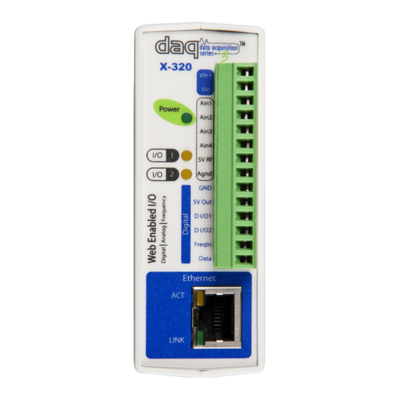
Section 1: Introduction X-320M™ contains a unique combination of dedicated meteorological instrument functions as well as general purpose control capability in a compact, cost-effective package. Like all ControlbyWeb products, X-320M is designed to operate through a web browser; no driver required, no subscription, no remote server, no script programming. - Page 9 - Password-protected interface. - Automatic time synchronization through NTP service. - Using the Remote Services interface, data from multiple X-320s and other ControlByWeb products can be aggregated under a common server. Figure 1.1b - Product Image Xytronix Research & Design, Inc.
-
Page 10: X-320M™ Features
Remote Analog (4) Expand sensor capability with up to 4 analog inputs from another device such as an X-320™ or Analog Module. Temperature or Humidity Digital Sensor Inputs (6) Monitor any combination of temperature or humidity sensors up to 600 ft away. -
Page 11: X-320M™ Models Available
X-320M™ User's Manual Introduction 1.2 X-320M™ Models Available X-320M™ is currently available in one model. X-320M-I Web-enabled Meteorological Station Controller 1.2.1 Optional Accessories Accessory Description Part Number Temperature Sensor Digital temperature sensor with 12 inch wire leads. X-DTS-U Note: Leads may be extended. Temperature Sensor Digital temperature sensor housed in vented plastic X-DTS-WM... -
Page 12: Connectors & Indicators
Introduction X-320M™ User's Manual 1.3 Connectors & Indicators Figure 1.4a - Connections & Indicators I/O Connector X-320M™ has a 14-position removable terminal connector. Which is used to provide power to the module and connect Digital I/O, Analog Inputs, Frequency Input, and Temperature/Humidity Sensor Inputs. -
Page 13: Accessing X-320M
X-320M™ User's Manual Introduction Ethernet Indicators The LINK LED is illuminated green when the module is properly connected to an Ethernet network and is ready to communicate. Network communications will only occur if this LED is illuminated. The ACT LED flashes amber when activity is detected on the network. 1.4 Accessing X-320M™... -
Page 14: Section 2: Installation And Setup
Installation and Setup X-320M™ User's Manual Section 2: Installation and Setup Installation consists of mounting X-320M™, connecting it to an Ethernet network, providing power, configuring via a web browser, and wiring the Digital I/O's, Analog Inputs, Frequency Inputs, and Temperature and/or Humidity Sensors. 2.1 Mounting X-320M™... -
Page 15: Connection
X-320M™ User's Manual Installation and Setup 2.2 Connection CAUTION: MAKE SURE POWER IS SHUT OFF BEFORE WIRING! CAUTION: THIS UNIT SHOULD BE INSTALLED BY A QUALIFIED TECHNICIAN. MIS-WIRING OR MIS-CONFIGURATION COULD CAUSE PERMANENT DAMAGE TO X-320M™, THE EQUIPMENT TO WHICH IT IS CONNECTED, OR BOTH. A removable terminal connector is provided for simple wiring. -
Page 16: Power Supply Connection
Installation and Setup X-320M™ User's Manual 14-pin Connector Pinout Description Power Supply VDC+. Vin+ 9-28 VDC for model X-320M-I. DO NOT EXCEED MAXIMUM POWER SUPPLY VOLTAGE. Vin- VDC- (Ground) power supply input. Analog Input 1 used with 0-5 V analog sensors, such as Ain1 temp, solar, humidity, and barometric pressure. -
Page 17: Digital Input/Output Connections
X-320M™ User's Manual Installation and Setup 2.2.2 Digital Input/Output Connections The Digital I/O's can be individually programmed to function as either inputs or outputs. When configured as inputs, pull-up or pull-down resistors can be programmed. For unconnected inputs, the pull resistors will be read as ON when pulled up, or OFF when pulled down. Input Connection The inputs can be configured to count the tips of the bucket in a rain collector, the rate of spin on a wind speed sensor, or detect switch closures on other connected devices, such as a lightning detector. - Page 18 Relays on other ControlByWeb devices can be controlled with X-320M through the Remote Relay feature. Up to two remote relays can be configured, each of which may be on a separate device.
-
Page 19: Analog Input
X-320M™ User's Manual Installation and Setup 2.2.3 Analog Input Voltage and current output sensors can be connected to X-320M analog inputs. Typical weather station analog sensors can measure temperature, humidity, solar radiation, barometric pressure, and soil moisture. Additionally, the analog inputs can function in a digital mode, activating alarms based on voltage thresholds. - Page 20 Installation and Setup X-320M™ User's Manual Wiring Considerations The analog inputs on X-320M™ are very sensitive (10 uV) and can be affected by low level noise. The Vin- on X-320M™ should be connected to earth ground. Additionally, all cable shields should be connected to earth ground.
- Page 21 X-320M™ User's Manual Installation and Setup 4-20 mA Sensors (Current level conveys information, not voltage levels) Some sensors are designed to change the output of the current instead of the voltage levels. To use these sensors, a resistor is placed in parallel with the sensors. Placing a resistor across the terminals of the sensor creates a voltage drop between them that changes as the current changes.
-
Page 22: Frequency Input
Installation and Setup X-320M™ User's Manual 2.2.4 Frequency Input Sensors that output a frequency can be connected to the Frequency Input. Connect one end of the sensor to FreqIn and the other to GND. Figure 2.2.g illustrates a wind speed sensor being connected to an X-320M™. -
Page 23: Digital Temperature/Humidity Sensor Connection
X-320M™ User's Manual Installation and Setup 2.2.5 Digital Temperature/Humidity Sensor Connection The digital sensors use a one-wire data bus, which allows up to six sensors to share the same terminals (+5V, Ground, Data). Every sensor on the one-wire bus is assigned a unique serial number when it is manufactured. - Page 24 Installation and Setup X-320M™ User's Manual Multiple sensors can be connected in two ways: directly connected to the unit (star topology) or “daisy chained” (linear topology) as shown in Figure 2.2i. Many factors will determine the maximum length of cable used to connect sensors to X-320M™. Some of these factors include, but are not limited to, the type of cable used, the number of sensors, ambient electromagnetic noise, and sensor network topology.
-
Page 25: Network Connection
X-320M™ User's Manual Installation and Setup Avoid sensor runs adjacent to industrial equipment power cables. These cables can have high current spikes that may induce noise on the sensor signals. Similarly, avoid running sensor cables near any radio transmission antennas or coaxial feed-lines. Protect any electrical connections with appropriate weather shielding. -
Page 26: Establishing Communications For Setup
X-320M™. Note: If multiple ControlByWeb™ products are used on the same network, install one at a time and set the IP address of each unit before connecting the next unit to the network. This avoids having multiple devices being installed on the network with the same factory default IP address at the same time. - Page 27 X-320M™ User's Manual Installation and Setup Linux/Unix Instructions 1. Open a terminal and change to root user (su -, then enter root password). 2. Type: arp -s {new IP address} {serial number of X-320M™ } Note: IP address format is xxx.xxx.xxx.xxx. The serial number can be found on a label on the module board.
-
Page 28: Method 2: Assign A Temporary Ip Address To Configuration Computer
Installation and Setup X-320M™ User's Manual 2.3.2 Method 2: Assign a Temporary IP Address to Configuration Computer If the foregoing option above is not used, you can use this option to communicate with X-320M™. By default, X-320M™ comes from the factory with an IP address of 192.168.1.2. Communications with X- 320M™... - Page 29 X-320M™ User's Manual Installation and Setup 2. Double click on the icon labeled Network Connections. The Network Connections window will open (Figure 2.3c). Figure 2.3c- Network Connection 3. Right click on the icon labeled Local Area Connection. In the menu that follows, select the option at the bottom of the menu labeled Properties.
- Page 30 Installation and Setup X-320M™ User's Manual 4. In the Local Area Connection Properties window in the Connection Uses box, scroll down and highlight “Internet Protocol (TCP/IPv4).” Click the button labeled Properties. The Internet Protocol (TCP/IPv4) Properties menu appears (Figure 2.3e). Note: If “Use the following IP address”...
-
Page 31: X-320M™ Setup
X-320M™ User's Manual Installation and Setup 2.4 X-320M™ Setup Pages X-320M™ is configured using a web browser. To access the setup pages, enter the following URL in the address bar of a web browser: http://{ipaddress}/setup.html For example, using the default IP address, enter: http://192.168.1.2/setup.html After the page is requested, a password prompt will appear. - Page 32 Installation and Setup X-320M™ User's Manual Serial Number This is the serial number of this unit. The serial number is also the MAC address of the unit. System Monitoring: Internal Temp: This displays the current temperature inside X-320M™. Note that it is normal for this to be significantly higher than room temperature.
-
Page 33: Network Tab
X-320M™ User's Manual Installation and Setup 2.4.2 Network Tab The network parameters are set on this page. Note: X-320M™ must be power-cycled (power disconnected, then reconnected) before network settings take effect. Only the settings on the Network tab require power-cycling before taking effect. Figure 2.4b - Network Tab Xytronix Research &... - Page 34 Installation and Setup X-320M™ User's Manual Use DHCP This option allows DHCP to be enabled or disabled. If this option is set to Yes, X-320M™ will wait for an IP address from a DHCP server each time it is powered. If DHCP is set to Yes, the Network page must be submitted and X-320M™...
- Page 35 X-320M™ User's Manual Installation and Setup 10 Mbps, it draws less power and runs a little cooler, which may translate into a longer product life. The default setting for this field is 10 Mbps. IT IS RECOMMENDED THAT THIS SETTING BE LEFT AT 10 Mbps UNLESS THE USER HAS A SPECIFIC REASON TO USE 100 Mbps.
- Page 36 Installation and Setup X-320M™ User's Manual Brief Notes About DHCP All devices on an IP network require an IP address. This is a unique address that identifies each device on the network. DHCP (Dynamic Host Control Protocol) is a mechanism that automatically assigns an IP address to a computer (or other devices) when it is connected to a network.
-
Page 37: Advanced Network Tab
X-320M™ User's Manual Installation and Setup 2.4.3 Advanced Network Tab Note: These settings are not used for most installations. Figure 2.4c - Advanced Network Tab Remote Services Enabled This option enables or disables Remote Services. If Yes is selected, Remote Services will be enabled as soon as the submit button is pressed and X-320M™... - Page 38 For additional security, X-320M™ has a simple built-in firewall. If desired, X-320M™ can be configured to only allow access to client devices (computers, servers, other ControlByWeb™ devices, etc) with certain IP addresses. Two IP address ranges are provided and only client devices with addresses that fall within those two ranges will be allowed access.
-
Page 39: Password Tab
X-320M™ User's Manual Installation and Setup Remote Services initiates the connection to the external web server (rather than the web server initiating communications to X-320M™). This has two main benefits. First, the web server does not need to know the IP address of X-320M™. This means that X-320M™ can get its IP address dynamically from a DHCP server, simplifying the installation. - Page 40 Installation and Setup X-320M™ User's Manual Control Password When the Enable Control Password option is set to Yes, this field is used to specify the password which will be required to access the Control Page. Passwords that are 8 characters or longer with both alphabetic and numeric characters are recommended (up to 13 characters can be entered in this field).
-
Page 41: Date/Time Tab
X-320M™ User's Manual Installation and Setup 2.4.5 Date/Time Tab X-320M™ uses the time for logging (a time stamp is included with each logged event). The time is stored and displayed in 24-hour time format. X-320M™ has a capacitor-backed real-time-clock circuit that will keep track of time for several days in the event of a power failure. - Page 42 Installation and Setup X-320M™ User's Manual Manual Time Configuration Date The current date is entered by first selecting the correct month and year, using the left and right arrows at the top of the calender. The single arrows (< and >) change the month and the double arrows (<<...
- Page 43 X-320M™ User's Manual Installation and Setup Public NTP servers can be found at www.pool.ntp.org. Some of these are listed below. US Servers (http://www.pool.ntp.org/zone/us): 0.us.pool.ntp.org 1.us.pool.ntp.org 2.us.pool.ntp.org 3.us.pool.ntp.org North America (http://www.pool.ntp.org/zone/north-america): 0.north-america.pool.ntp.org 1.north-america.pool.ntp.org 2.north-america.pool.ntp.org 3.north-america.pool.ntp.org Europe (http://www.pool.ntp.org/zone/europe): 0.europe.pool.ntp.org 1.europe.pool.ntp.org 2.europe.pool.ntp.org 3.europe.pool.ntp.org Australia (http://www.pool.ntp.org/zone/au): 0.au.pool.ntp.org 1.au.pool.ntp.org...
- Page 44 Installation and Setup X-320M™ User's Manual Note: If X-320M™ will lose power on a frequent basis, it may be beneficial to set this option to No, as some servers are configured to dis-allow access from client devices that excessively request their services.
-
Page 45: Logging Tab
X-320M™ User's Manual Installation and Setup 2.4.6 Logging Tab X-320M™ can be configured to record data such as wind speed and direction, temperature, and solar radiation. The logged data is stored in internal non-volatile memory and can be retrieved by entering the command http://{X-320M IP address}/log.txt. - Page 46 Installation and Setup X-320M™ User's Manual the start time is 01:00 and the logging rate is 6 hours, logging will occur at 01:00, 07:00, 13:00, and 19:00. Start time is specified in 24-hour time format. The default setting for this field is 01:00. Logging Rate This field is used to specify the time period of logging.
-
Page 47: Remote Devices Tab
Note: Remote Relay 1 and 2 can be separate remote devices. - Remote Analog: This allows you to receive analog data from another ControlByWeb devices that features Analog Inputs, such as the X-320, X-320M, or Analog Module. Up to 4 single-ended analog inputs from a device can be read. - Page 48 If the remote device has multiple relays, this field should be set to the relay number. For example, if relay 2 is to be controlled on another ControlByWeb™ product, the Relay # would be set to 2. This field can be set from 0 to 255.
-
Page 49: I/O Tab
X-320M™ User's Manual Installation and Setup 2.4.8 I/O Tab This page provides configuration options for the two Digital I/O's built into X-320M™. The Digital I/O may be configured as inputs or outputs. Different configuration pages are used for each of these modes. Figure 2.4i - Digital I/O Tab - Input Configuration Digital I/O A drop-down menu is used to select the control input to which the options below will apply. - Page 50 Installation and Setup X-320M™ User's Manual Counter Options The inputs can be used as counters. This field specifies counter operation. Note that the input voltage must remain on or off for the minimum hold time (debounce time) before the counter will be incremented.
- Page 51 X-320M™ User's Manual Installation and Setup Output Mode The following paragraphs describe the Digital Output mode configuration shown in Figure 2.4j. Figure 2.4j - Digital I/O Tab - Output Configuration State at Powerup This drop-down menu lets the user specify the state of each of the output when X-320M™ is powered up.
-
Page 52: Status Setup Tab
Installation and Setup X-320M™ User's Manual 2.4.9 Status Setup Tab This page is used to provide detailed information about the site where X-320M™ is installed, as well as Status Page configuration settings. Figure 2.4k - Site Information Tab Figure 2.4k - Status Setup Tab Site Description This text field is used to describe the site where X-320M™... - Page 53 External Link Address This text field is used to provide a direct link to another website or webpage. Up to 96 characters can be entered into this field. The default external link address is www.controlbyweb.com. Xytronix Research & Design, Inc.
-
Page 54: Wind Speed Tab
Installation and Setup X-320M™ User's Manual 2.4.10 Wind Speed Tab This page provides options for configuring the Wind Speed sensor input. Additional information about the Wind Speed calculations can be found in Appendix F: Methods and Calculation Details. Figure 2.4l - Wind Speed Tab Page 54 Xytronix Research &... - Page 55 - Rmt Analog 1-4: This option is used if the connected sensor is an analog sensor that is being read from a remote Analog device, such as another X-320™ or Analog Module. Slope In many cases, the inputs must be scaled to represent “real-world” measurements. X-320M™ reads the “raw”...
- Page 56 Installation and Setup X-320M™ User's Manual Units This drop-down allows you to specify the units of measure for the wind speed sensor. The units selected will be determined by the Slope and Offset used to calibrate the sensor. The following options are available: - mph: This option is used if you are measuring the wind speed in miles per hour.
- Page 57 - High or Low Alarm: The specified output action occurs due to the High and/or Low Alarm. Remote Relay 1-2 The X-320M™ can be configured to control relays in other ControlByWeb™ products that are located at a remote locations on the network. This field determines the action taken by Remote Relay due to an alarm condition.
- Page 58 Installation and Setup X-320M™ User's Manual Remote Services This field specifies the action with a remote server due to an alarm condition. The following actions are available: - No Action: No action is taken. - Send Message: state.xml will be sent to the remote server. The second drop down box specifies the conditions that will cause an alarm trigger.
-
Page 59: Wind Direction Tab
- Rmt Analog 1-4: This option is used if the connected sensor being used is an analog sensor that is being read from a remote Analog device, such as another X-320™ or Analog Module. Xytronix Research & Design, Inc. - Page 60 Installation and Setup X-320M™ User's Manual Slope In many cases, the inputs must be scaled to represent “real-world” measurements. X-320M™ reads the “raw” value from each input, and calculates the number that represents the “real-world” measurement that the user is actually interested in. This real-world value (referred to as the “Scaled Value”...
-
Page 61: Rain Tab
X-320M™ User's Manual Installation and Setup 2.4.12 Rain Tab This page provides options for configuring the Rain Accumulation sensor input. Additional information about the Rain gauge calculations can be found in Appendix F: Methods and Calculation Details. Figure 2.4o - Rain Sensor Tab Sensor Connection This drop-down menu allows you to select which type of input you are using to monitor rain accumulation. - Page 62 Installation and Setup X-320M™ User's Manual Slope In many cases, the inputs must be scaled to represent “real-world” measurements. X-320M™ reads the “raw” value from each input, and calculates the number that represents the “real-world” measurement that the user is actually interested in. This real-world value (referred to as the “Scaled Value”...
- Page 63 - High Alarm: The specified output action occurs due to High Alarm. Remote Relay 1-2 X-320M™ can be configured to control relays in other ControlByWeb™ products that are located at a remote location on the network. This field determines the action taken by Remote Relay due to an alarm condition.
-
Page 64: Temperature Tab
Installation and Setup X-320M™ User's Manual 2.4.13 Temperature Tab This page provides options for configuring the Temperature sensor input. Additional information about the Temperature calculations can be found in Appendix F: Methods and Calculation Details. Figure 2.4p - Temperature Tab Sensor Connection This drop-down menu allows you to select which type of input you are using to monitor temperature. - Page 65 - Rmt Analog 1-4: This option is used if the connected sensor is an analog sensor that is being read from a remote Analog device, such as another X-320™ or Analog Module. 1-Wire Address (only shown if 1-Wire Bus is selected in Sensor Connection) Each 1-Wire sensor comes from the factory with a unique, non-changeable address.
- Page 66 Installation and Setup X-320M™ User's Manual High Alarm This setting is used to set the trigger point for a high alarm condition. The number field specifies the temperature at which the alarm is triggered. An alarm is triggered when the sensor reading exceeds the High Alarm value.
- Page 67 X-320M™ User's Manual Installation and Setup Email Option Simple email messages can be sent in response to alarm conditions. This parameter is used to specify what alarm conditions, if any, will cause email messages to be sent. Note that email notification will work only if email is correctly set up in the Network setup page.
- Page 68 X-320M™ User's Manual Remote Relay 1-2 X-320M™ can be configured to control relays in other ControlByWeb™ products that are located at a remote location on the network. The same actions for the local outputs also apply to remotely controlled relays. This field determines the action taken by Remote Relay due to an alarm condition.
-
Page 69: Humidity Tab
X-320M™ User's Manual Installation and Setup 2.4.14 Humidity Tab This page provides options for configuring the Humidity sensor input. Additional information about the Humidity calculations can be found in Appendix F: Methods and Calculation Details. Figure 2.4r - Humidity Tab Sensor Connection This drop-down menu allows you to select which type of input you are using to monitor humidity. - Page 70 - Rmt Analog 1-4: This option is used if the connected sensor is an analog sensor that is being read from a remote Analog device, such as another X-320™ or Analog Module. 1-Wire Address (only shown if 1-Wire Bus is selected in Sensor Connection) Each 1-Wire sensor comes from the factory with a unique, non-changeable address.
- Page 71 X-320M™ User's Manual Installation and Setup Deadband The Deadband prevents alarms from triggering excessively when the sensor measurement vacillates around the trigger point. With High Alarms, the measurement must fall below the High Alarm point minus the Deadband before the High Alarm will be triggered again. Likewise, the Deadband on the Low Alarm requires the measurement to rise above the Low Alarm point plus the Deadband before the low alarm will be triggered again.
- Page 72 - High or Low Alarm: The specified output action occurs due to the High and/or Low Alarm. Remote Relay 1-2 X-320M™ can be configured to control relays in other ControlByWeb™ products that are located at a remote location on the network. The same actions for the local outputs also apply to remotely controlled relays.
-
Page 73: Solar Radiation Tab
X-320M™ User's Manual Installation and Setup 2.4.15 Solar Radiation Tab This page provides options for configuring the Solar Radiation sensor input. Additional information about the Solar Radiation calculations can be found in Appendix F: Methods and Calculation Details. Figure 2.4t - Solar Radiation Tab Xytronix Research &... - Page 74 - Rmt Analog 1-4: This option is used if the sensor being used is an analog sensor that is being read from a remote Analog device, such as another X-320™ or Analog Module. Slope In many cases, the inputs must be scaled to represent “real-world” measurements. X-320M™ reads the “raw”...
- Page 75 X-320M™ User's Manual Installation and Setup Deadband The Deadband prevents alarms from triggering excessively when the sensor measurement vacillates around the trigger point. With High Alarms, the measurement must fall below the High Alarm point minus the Deadband before the high alarm will be triggered again. Likewise, the deadband on the Low Alarm requires the measurement to rise above the Low Alarm point plus the Deadband before the Low Alarm will be triggered again.
- Page 76 - High or Low Alarm: The specified output action occurs due to the High and/or Low Alarm. Remote Relay 1-2 X-320M™ can be configured to control relays in other ControlByWeb™ products that are located at a remote location on the network. This field determines the action taken by Remote Relay due to an alarm condition.
-
Page 77: Barometric Pressure Tab
X-320M™ User's Manual Installation and Setup 2.4.16 Barometric Pressure Tab This page provides configuration options for configuring the Barometric Pressure sensor input. Additional information about the Barometric Pressure calculations can be found in Appendix F: Methods and Calculation Details. Figure 2.4v - Barometric Pressure Tab Sensor Connection This drop-down menu allows you to select which type of input you are using to monitor barometric pressure. - Page 78 - Rmt Analog 1-4: This option is used if the connected sensor is an analog sensor that is being read from a remote Analog device, such as another X-320™ or Analog Module. Slope In many cases, the inputs must be scaled to represent “real-world” measurements. X-320M™ reads the “raw”...
- Page 79 X-320M™ User's Manual Installation and Setup High Alarm This setting is used to set the trigger point for a high alarm condition. The alarm is triggered when the value at the sensor exceeds the High Alarm Value. The default High Alarm is 20. Low Alarm This setting is used to set the trigger point for a low alarm condition.
- Page 80 - High or Low Alarm: The specified output action occurs due to the High and/or Low Alarm. Remote Relay 1-2 X-320M™ can be configured to control relays in other ControlByWeb™ products that are located at a remote location on the network. This field determines the action taken by Remote Relay due to an alarm condition.
-
Page 81: Aux1 And Aux2 Tab
X-320M™ User's Manual Installation and Setup 2.4.17 AUX1 and AUX2 Tab The AUX1 and AUX2 setup pages allow you to configure additional sensors that are not listed under the default setup tabs. Figure 2.4x - AUX 1 and 2 Tab Sensor Connection This drop-down menu allows you to select which type of AUX input you are using. - Page 82 - Rmt Analog 1-4: his option is used if the AUX1 or AUX2 sensor used is an analog sensor that is being read from a remote Analog device, such as another X-320™ or Analog Module. 1-Wire Address (only shown if 1-Wire Bus is selected in Sensor Connection) Each 1-Wire sensor comes from the factory with a unique, non-changeable address.
- Page 83 X-320M™ User's Manual Installation and Setup Deadband The Deadband prevents alarms from triggering excessively when the sensor measurement vacillates around the trigger point. With High Alarms, the measurement must fall below the High Alarm point minus the Deadband before the High Alarm will be triggered again. Likewise, the Deadband on the Low Alarm requires the measurement to rise above the Low Alarm point plus the deadband before the Low Alarm will be triggered again.
- Page 84 - High or Low Alarm: The specified output action occurs due to the High and/or Low Alarm. Remote Relay 1-2 X-320M™ can be configured to control relays in other ControlByWeb™ products that are located at a remote location on the network. This field determines the action taken by Remote Relay due to an alarm condition.
-
Page 85: Section 3: Operation
X-320M™ User's Manual Operation Section 3: Operation X-320M™ can be operated using a web browser, or by sending text commands to an XML status/control page. X-320M™ also allows you to control the outputs using inputs, or alarms. Note: Using an input or alarm to control the outputs was described throughout previous sections of the manual, and will not be described here. - Page 86 Operation X-320M™ User's Manual Temperature Display of the current temperature, current High and Low temperature values for today, and these values for yesterday. High/Low Alarm status. Calculated Values This row displays the calculated values for the Heat Index, Wind Chill and Dew Point based off current wind and temperatures.
- Page 87 X-320M™ User's Manual Operation External Link Displays a link provided by the user to an external site or webpage. Configurable in the Status Setup tab. Date/Time Displays the current time that is set using the Date/Time tab in the setup pages. Note: Information about how these values are measured and calculated can be found in Appendix F: Methods and Calculation Details.
-
Page 88: Xml Operation
Operation X-320M™ User's Manual 3.2 XML Operation Custom XML computer applications may be created to monitor and control X-320M™. This method does not use a web browser. There are three XML pages that can be used to monitor or control X-320M™: state.xml, eventX.xml. - Page 89 X-320M™ User's Manual Operation <presN24>30.14</presN24> <presAlrm>1</presAlrm> <windGust>47.00</windGust> <windAlrm>2</windAlrm> <serialNumber>00:0C:C8:00:00:09</serialNumber> <time>1309963843</time> </datavalues> The numbers enclosed by the tags, <tag>, indicate the current state or value monitored by X-320M™. Values for each tag are described in the table below. XML computer applications will open a TCP/IP socket with X-320M™ and send a GET command followed by the state.xml command string.
- Page 90 Operation X-320M™ User's Manual XML Tags Monitor Values <windChill> Indicates the calculated wind chill value. <dewPoint> Indicates the calculated dew point. <tempAlrm> Current state of the temperature alarm. 0 = Normal 1 = High 2 = Low <humidityH> Indicates today's highest humidity reading. <humidityL>...
- Page 91 X-320M™ User's Manual Operation XML Control Commands can be sent to X-320M™ to control the outputs, counters, and external variables. Output State Control Commands are sent using a variable called relayXState (X is replaced by 1 for Output 1, or 2 for Output A few examples of using relayXState are given below.
- Page 92 Operation X-320M™ User's Manual Message Acknowledgment By default, when commands are sent to X-320M™, the state.xml page is returned. The XML reply can be disabled by adding the noReply field as follows: Command Description state.xml?relay1State=1&noReply=1 Turn Output 1 ON without returning state. state.xml?relay1State=0&noReply=1 Turn Output 1 OFF without returning state.
-
Page 93: Diagnostics.xml
X-320M™ User's Manual Operation 3.2.2 Diagnostics.XML There is a special diagnostics.xml that can be requested by entering the following in the web browser address bar: http://192.168.1.2/diagnostics.xml The following diagnostics.xml file is returned: <datavalues> <internalTemp>43.5</internalTemp> <vin>16.5</vin> <internal6Volt>6.2</internal6Volt> <memoryPowerUpFlag>1</memoryPowerUpFlag> <devicePowerUpFlag>1</devicePowerUpFlag> <powerLossCounter>3</powerLossCounter> </datavalues> Diagnostic tags are given in the table below. -
Page 94: Get Requests
Authorization: Basic bm9uZTp3ZWJyZWxheQ== (Terminated with two \r\n.) bm9uZTp3ZWJyZWxheQ== is the Base64 encoded version of the user “name:password,” none:webrelay. A utility is provided at http://www.controlbyweb.com/encoder to encode the password. Simply type the string username:password into the website and press 'Encode'. Page 94... -
Page 95: Email Notification
X-320M™ User's Manual Operation 3.4 Email Notification 3.4.1 Email Notification Description X-320M™ can be configured to send messages to five email addresses when a sensors alarm point is reached. Sensors that are connected to X-320M™ and configured can generate an email message When an email message is sent, it will look similar to this: MET Station Trigger: RAIN - High Alarm... - Page 96 Operation X-320M™ User's Manual User Name (If Required) Password (If Required) Return Email Email 1 Email 2 Email 3 Email 4 Email 5 Note: X-320M™ must be power-cycled (power disconnected, then reconnected) before network settings take effect. Only the settings on the Network tab require power-cycling before taking effect. The email options and recipients for each monitored value can be configured separately.
-
Page 97: Appendix A: Restoring Factory Default Settings
X-320M™ User's Manual Appendix A: Restoring Factory Default Settings Appendix A: Restoring Factory Default Settings In the event that the IP address or passwords are forgotten, X-320M™ may be restored to its original factory default settings. 1. Remove the DC power from the unit. 2. -
Page 98: Appendix B: Installing New Firmware
Setup 1. Download the firmware zip file from the ControlByWeb website. Only a X-320M™ image can be installed on X-320M™ so make sure the correct image is being downloaded. 2. bootloader.exe will connect to X-320M™ using default IP address 192.168.1.2, not the address currently assigned to X-320M™. - Page 99 3. While holding the reset button, apply power to X-320M™. The LINK and ACT lights will flash. Continue to hold the reset button for the next step. 4. While holding the reset button, press the Upload Firmware button at the bottom of the ControlByWeb™ Programmer window. After the programming process begins, the reset button can be released 5.
-
Page 100: Appendix C: Accessing X-320Tm Over The Internet
Appendix C: Accessing X-320TM Over the Internet X-320M™ User's Manual Appendix C: Accessing X-320 Over the Internet X-320M™ can be monitored and/or controlled from a remote location over the Internet. Once X-320M™ can be accessed on the local network, almost all of the settings required to provide remote access are in the router and not in X-320M™. - Page 101 X-320M™ User's Manual Appendix C: Accessing X-320TM Over the Internet Figure Appendix C.1 - Local Area Network A Simple LAN connected to the Internet The LAN in the example above can be connected to the Internet by adding a router and an Internet connection.
- Page 102 65235. However, many port numbers are reserved for specific applications and should be avoided. As a general rule, numbers above 8000 are safe to use. All of the ControlByWeb™ products come from the factory with the HTTP port set to 80, which is the standard port for HTTP. In this example, X-320M™...
- Page 103 For example, to access the setup pages when the port is set to 8000, the following command would be used: http://192.168.1.25:8000/setup.html To access the ControlByWeb™ units from the Internet, enter the public IP address of the router plus the port number of the desired device in the following format: http://(Public IP Address of Router):(Port Number of Device)/setup.html Using the example above, the following line would be used to access the setup page of X-320M™:...
-
Page 104: Appendix D: External Server And Remote Services
An external web server can integrate multiple ControlByWeb products into a single control page. In other words, the user may not be aware that he/she is using multiple ControlByWeb™ devices, but rather the user sees an integrated control page for the entire system. In addition, the use of an external web server... - Page 105 X-320M™ User's Manual Appendix D: External Server and Remote Services required. This makes the network installation of X-320M™ very simple, and since no incoming ports need to be opened in the router, security is not compromised. See section 2.4.3 Advanced Network Tab for more information.
-
Page 106: Appendix E: Log Files
Appendix E: Log Files X-320M™ User's Manual Appendix E: Log Files X-320M™ logs information to two different log files: log.txt and syslog.txt. Both log files are text files and are stored in nonvolatile memory. This data will not be lost due to power failure and is also not cleared when restoring factory defaults. - Page 107 X-320M™ User's Manual Appendix E: Log Files System Log File – syslog.txt The syslog file records various system events, which can be used for diagnostics and troubleshooting purposes. File Format: MM/DD/YYYY HH:MM:SS, (category to which message applies): (message) Sample File: 01/02/2010 04:08:13 DEVICE: Power Up.
- Page 108 Appendix E: Log Files X-320M™ User's Manual This file is read by requesting the syslog.txt file. For example, using the default IP address, the following command would be used: http://192.168.1.2/syslog.txt Note: The setup user name and password are required to access this file. If the TCP port has been changed (not port 80), the port will be required to read the file.
-
Page 109: Appendix F: Methods And Calculation Details
X-320M™ User's Manual Appendix F: Methods and Calculation Details Appendix F: Methods and Calculation Details The following section describes the methods and calculations used for X-320M™ instrument measurements and derived values. Sensor Acquisition Periods Sensors connected to X-320M™ are sampled or updated every 2 seconds. Analog values are captured every two seconds. - Page 110 Appendix F: Methods and Calculation Details X-320M™ User's Manual new readings are made, the oldest values are replaced. If the averaging period is set to 0, then the instantaneous Wind Direction is given. Note: Wind Speed and Wind Direction use the same Averaging Period. For example, if the Averaging Period is changed from 2 minutes to 4 minutes, both Wind Speed and Direction will be changed to 4 minutes.
- Page 111 X-320M™ User's Manual Appendix F: Methods and Calculation Details Barometric Pressure The Barometric Pressure reading is the instantaneous reading, no averaging is done. Once an hour, the current Barometric Pressure is stored. This provides an hourly history for the past 24-hours. By default, the station will give an absolute pressure reading.
- Page 112 Appendix F: Methods and Calculation Details X-320M™ User's Manual Dew Point Dew Point is based on Temperature and Humidity. The most recent Temperature and Humidity values are used for this calculation. Dew Point will only be calculated when the Temperature is between 0ºC - 60ºC, and the Humidity is greater than or equal to 1%RH.
-
Page 113: Appendix G: Common Sensor Setup Parameters
X-320M ™ is easily adapted to the Davis Integrated Sensor Suite (ISS) by using the Davis adapter board, Xytronix product number X-MDA-1. Please refer to X-MDA-1 product information on the ControlByWeb web site. Wind Speed X-320M™ can utilize the frequency input or either of the digital inputs for wind speed. Wind speed sensors predominately use one of two methods, frequency generator or reed switch closure. - Page 114 Appendix G: Common Sensor Setup Parameters X-320M™ User's Manual Make Model Output Slope Offset Settings Connections Davis 7852 N.O. Reed in: 0.01 I/O: Input, Pull-Up, Digital Input Switch Increment when input off mm: 0.254 Ground 52203 N.O. Reed in: 0.00394 I/O: Input, Pull-Up, Digital Input Young...
- Page 115 X-320M™ User's Manual Appendix G: Common Sensor Setup Parameters Humidity X-320M™ can be used with 1-Wire humidity/temperature sensor such as Xytronix X-DTHS-WM. Linear response analog sensors (voltage or current output) may also be used. Non-linear thermistors are not compatible. The use of 1-Wire sensors has the advantage of allowing multiple sensors to be installed and frees up analog ports for other sensor options.
- Page 116 Appendix G: Common Sensor Setup Parameters X-320M™ User's Manual Barometric Pressure Barometric Pressure sensors are typically installed on the analog input ports. Make Model Output Slope Offset Connections Apogee SB-110 0-5 VDC hPa: 218 hPa: 114 5Vout Instruments approx mmHg: 6.437 mmHg: 6.437 Data approx.
-
Page 117: Appendix H: Specifications
X-320M™ User's Manual Appendix H: Specifications Appendix H: Specifications Power Requirements - Input Voltage: 9-28 VDC - Current: See table below for typical values at 25°C. 10 Mbps Network Speed Power Supply Digital Outputs Digital Inputs w/ Pull Resistors All Off All On Pull-up Pull-down... - Page 118 Appendix H: Specifications X-320M™ User's Manual Pulse Counters - See Digital Input Mode - 2 second average - 0.5 Hz read rate Frequency Input - 0-130 kHz input frequency - AC or DC input, 20 V peak to peak - Sine or square wave (Triangle wave, add 10% to Min Vin) - 2 second average - 0.5 Hz read rate - Auto-zero, positive slope detection...
- Page 119 X-320M™ User's Manual Appendix H: Specifications 5 LED Indicators - Power On - I/O (1-2) - Network Linked - Network Activity Real-Time Clock - Manual or NTP (Network Time Protocol) setup - NTP Sync Configurable for Once, Daily, Weekly, or On Power-up - Automatic Daylight Savings Adjustment - Battery (capacitor) Power Backup Capacitor Power Backup...
-
Page 120: Appendix I: Mechanical Information
Appendix I: Mechanical Information X-320M™ User's Manual Appendix I: Mechanical Information Page 120 Xytronix Research & Design, Inc. - Page 121 X-320M™ User's Manual Appendix I: Mechanical Information Alphabetical Index Password............31, 94 1-Wire Bus........... 65, 70, 82, 118 Username............39 10 Base-T............25, 118 DHCP..............34, 36 10/100 Base-T............25 Digital Temperature..........23 DIN-Rail..............14 DNS Server..............34 Advanced Network Tab...........37 DS18B20............... 118 Alarm...............
- Page 122 Appendix I: Mechanical Information X-320M™ User's Manual Rain..............110 Scaled Value....55, 60, 62, 65, 70, 74, 78, 82 Solar Radiation..........1 10 Security..........7, 38, 104, 105 Temperature............110 Sensor..............11 Wind Direction..........1 09 Alarm..............67 Wind Speed ............109 Cable.............24, 25 Deadband............
Need help?
Do you have a question about the X-320 and is the answer not in the manual?
Questions and answers