Table of Contents
Advertisement
Available languages
Available languages
Quick Links
USE AND CARE GUIDE
Questions, problems, missing parts? Before returning to the store,
8 a.m. - 7 p.m., EST, Monday-Friday, 9 a.m. - 6 p.m., EST Saturday
We appreciate the trust and con dence you have placed in Hampton Bay through the purchase of this ceiling fan. We strive to
continually create quality products designed to enhance your home. Visit us online to see our full line of products available for
your home improvement needs. Thank you for choosing Hampton Bay!
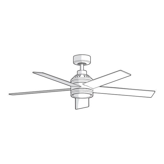
52 IN. ASHBURROW
INDOOR CEILING FAN
call Hampton Bay Customer Service
1-855-HD-HAMPTON
HAMPTONBAY.COM
Visual instruction of how to install this fan:
Visit www.homedepot.com and enter either the Item or Model number to nd
this fan and click the link of visual instruction in the product overview section.
THANK YOU
Item #1011954834
1011954839
Model #AK641-BN
AK641-MBK
Advertisement
Table of Contents

Related Manuals for HAMPTON BAY ASHBURROW AK641-BN


Summary of Contents for HAMPTON BAY ASHBURROW AK641-BN
- Page 1 THANK YOU We appreciate the trust and con dence you have placed in Hampton Bay through the purchase of this ceiling fan. We strive to continually create quality products designed to enhance your home. Visit us online to see our full line of products available for...
-
Page 2: Table Of Contents
Table of Contents Table of Contents ........Assembly . -
Page 3: Warranty
Warranty The manufacturer warrants the fan motor to be free from defects in workmanship and material present at time of shipment from the factory for a period of lifetime after the date of purchase by the original purchaser. The manufacturer warrants the light kit (excluding any glass), to be free from defects in workmanship and material at the time of shipment from the factory for a period of three years after the date of purchase by the original purchaser. -
Page 4: Hardware Included
Pre-Installation (continued) HARDWARE INCLUDED NOTE: Hardware not shown to actual size. Part Description Quantity Plastic wire nut Blade attachment screw with lock washer (additional) 1.5V AAA battery 3-pin extension cord... -
Page 5: Package Contents
Pre-Installation (continued) PACKAGE CONTENTS ON / OFF ON / OFF 3 SPEED BRIGHTNESS UP COLOR TEMP. COLOR TEMP. UP LIGHT. Part Description Quantity Part Description Quantity Mounting bracket (preassembled) Blade Canopy Blade support plate with screw and lock washer Canopy bottom cover (preassembled) Hanger ball/downrod assembly 20 watt LED light kit Coupling cover... -
Page 6: Installation
Installation MOUNTING OPTIONS NOTE: You may need a longer downrod to maintain proper WARNING: To reduce the risk of re, electric shock, or blade clearance when installing on a steep, sloped ceiling. personal injury, mount the fan to an outlet box marked The maximum angle allowable is 18°... -
Page 7: Assembly
Assembly Preparing the canopy Attaching the fan blades Remove the canopy bottom cover (C) from the canopy (B) by WARNING: To reduce the risk of personal injury, do not turning the canopy bottom cover (C) counterclockwise. bend the blades (G) while installing, balancing the blades (G), or cleaning the fan. -
Page 8: Assembling The Fan
Assembly (continued) Preparing the motor Assembling the downrod Flip the assembly. Remove the cotter pin and clevis pin, WARNING: Failure to properly install the cotter pin could and loosen the two collar set screws from the motor collar. result in the fan loosening and possibly falling. Lossen the set screw located in the hanger ball, lower the Carefully feed the motor wires up through the downrod. -
Page 9: Installing The Receiver
Assembly — Hanging the Fan Attaching the mounting bracket to the Hanging the fan on the mounting electrical box bracket WARNING: The tab in the ring must rest in the groove of the WARNING: To reduce the risk of re, electric shock or other hanger ball/downrod assembly (D). -
Page 10: Making The Electrical Connections
Assembly — Hanging the Fan (continued) Making the electrical connections Turn the wire nut connections upward, spreading them apart WARNING: To avoid possible electrical shock, be sure so the green (ground) and white wires will be on one side of electricity is turned off at the main fuse box before wiring. - Page 11 Assembly — Hanging the Fan (optional) Single Switch Connections Dual Switch Connections On a single switch the fan and light can be turned on or off On a dual switch the fan and light can be turned on or off together.
-
Page 12: Installing The Canopy
Assembly — Hanging the Fan (continued) Installing the canopy Attaching the canopy bottom cover NOTE: Adjust the canopy mounting screws as necessary until WARNING: Make sure the tab on the mounting bracket (A) the canopy (B) and canopy bottom cover (C) are snug. properly sits in the groove in the hanger ball before attaching the canopy (B) to the mounting bracket (A) by turning the canopy housing until it drops into place. - Page 13 Assembly — Installing the Light Kit Attaching the LED light kit to the light kit mounting ring CAUTION: Before starting installation, disconnect the power by turning off the circuit breaker or removing the fuse at the fuse box. Turning power off using the fan switch is not suf cient to prevent electric shock.
-
Page 14: Operation
Operation SETTING UP THE TRANSMITTER NOTE: The remote has been pre-paired in the factory for your convenience. NOTE: Batteries will weaken with age and should be replaced before leaking takes place as this will damage the remote control. Dispose of used batteries properly and keep them out of the reach of children. -
Page 15: Operation (Optional)
Operation (optional) OPERATING YOUR FAN AND REMOTE CONTROL NOTE: The fan will store the last used speed setting for the next time it is turned on. Power ALL button: Press and release the power button to turn the fan and light on or off. Signal light Power on/off Fan ON/OFF button: Press and release this button to turn the... -
Page 16: Installing The Remote Control Holder
Operation (optional) INSTALLING THE REMOTE CONTROL HOLDER NOTE: The remote wall cradle is designed to allow you to access an existing switch. The remote wall cradle can be mounted on the wall or to the face plate of a standard toggle switch or a paddle switch. - Page 17 Operation (optional) REVERSE SWITCH OPERATING INSTRUCTIONS The reverse switch is located on the top of the motor housing. Slide the switch to the left for warm weather operation. Slide the switch to the right for cool weather operation. Reverse switch NOTE: Wait for the fan to stop before reversing the direction of the blade rotation.
-
Page 18: Care And Cleaning
Care and Cleaning Check the support connections, brackets, and blade attachments twice a year. Make sure they are secure. Because of the fan’s natural movement, some connections may become loose over time. It is not necessary to remove the fan from the ceiling. Clean your fan periodically. - Page 19 - Consult the dealer or an experienced radio/TV technician for help. Questions, problems, missing parts? Before returning to the store, call Hampton Bay Customer Service 8 a.m. – 7 p.m., EST, Monday – Friday, 9 a.m. – 6 p.m., EST, Saturday 1-855-HD-HAMPTON HAMPTONBAY.COM...
- Page 20 GRACIAS POR TU COMPRA Apreciamos la con anza que has depositado en Hampton Bay al comprar este ventilador de techo. Nos esforzamos para continuamente crear productos de calidad diseñados para mejorar tu hogar. Visítanos por Internet para ver nuestra línea completa...
-
Page 21: Información De Seguridad
Índice Índice ......... . Ensamblado . -
Page 22: Especificaciones
Garantía El fabricante garantiza de por vida, a partir de la fecha en que el comprador original lo adquiere, que el motor del ventilador no presenta defectos de fabricación ni de material al momento en que es enviado desde la fábrica. El fabricante garantiza, por un período de tres años a partir de la fecha de compra por el comprador original, el kit de luces, sin incluir ningun de vidrio, no presentarán ningún defecto de fabricación o de material desde el momento de su salida de la fábrica. -
Page 23: Herrajes Incluidos
Pre-Instalación (continuación) HERRAJES INCLUIDOS NOTA: El hardware no se muestra en tamaño real. Pieza Descripción Cantidad Tuerca de conexión de cables de plástico Tornillo de jación de aspas y arandela de seguridad (adicional) Batería AAA de 1.5V Cable de extensión de 3-pine... -
Page 24: Contenido Del Paquete
Pre-Instalación (continuación) CONTENIDO DEL PAQUETE ON / OFF ON / OFF 3 SPEED BRIGHTNESS UP COLOR TEMP. COLOR TEMP. UP LIGHT. Pieza Descripción Cantidad Pieza Descripción Cantidad Soporte de montaje (preensamblado) Aspa Cubierta Placa de soporte para las aspa con tornillo y arandela de seguridad Tapa del fondo de la cubierta (preensamblado) Ensamblado de tubo bajante/bola de soporte... -
Page 25: Instalación
Instalación OPCIONES DE MONTAJE NOTA: Tal vez necesites un tubo bajante más largo para ADVERTENCIA: Para disminuir el riesgo de incendio, mantener la altura mínima adecuada de las aspas al instalar descarga eléctrica o lesiones personales, monta el ventilador sobre una caja eléctrica marcada como “aprobada como el ventilador en un techo inclinado. - Page 26 Ensamblado Cómo preparar la cubierta Cómo montar las aspas del ventilador Retira la tapa del fondo de la cubierta (C) de la cubierta (B), ADVERTENCIA: Para reducir el riesgo de lesiones personales, girando la cubierta del fondo de la cubierta (C) hacia la no doblar los de las aspas (G) durante la instalación, compensación izquierda.
- Page 27 Ensamblado (continuación) Cómo preparar el motor Cómo montaje de la varilla Da la vuelta al motor. Retira el pasador de chaveta y pasador ADVERTENCIA: Si no instalas correctamente el pasador de tipo horquilla, y a oja los dos tornillos de ajuste de collarín chaveta (FF) es posible que el ventilador se a oje y caiga.
-
Page 28: Instalación Del Receptor
Ensamblado — Cómo Colgar el Ventilador Cómo instalar el soporte de montaje Cómo colgar el ventilador al soporte en la caja eléctrica de montaje ADVERTENCIA: Para disminuir los riesgos de incendio, ADVERTENCIA: La pestaña en el anillo debe encajar en la descarga eléctrica o lesiones personales. -
Page 29: Cómo Hacer Las Conexiones Eléctricas
Ensamblado — Cómo Colgar el Ventilador (continuación) Cómo hacer las conexiones eléctricas Del ventilador A la caja de eléctrica ADVERTENCIA: Para evitar una posible descarga eléctrica, Cables verdes* --------------- Cable verde o desnudo asegúrate de que la electricidad esté apagada de la caja de (tierra) fusibles principal antes de realizar el cableado. - Page 30 Ensamblado — Cómo Colgar el Ventilador (opcional) Conexiones de un solo interruptor Conexiones de interruptor doble Con un solo interruptor, el ventilador y la luz se pueden En un interruptor doble, el ventilador y la luz se pueden encender o apagar por separado. Realice las conexiones de encender o apagar juntos.
- Page 31 Ensamblado — Cómo Colgar el Ventilador (continuación) Cómo sujetar la tapa del fondo de Cómo instalar la cubierta la cubierta NOTA: Ajusta los tornillos de montaje de la cubierta según ADVERTENCIA: Asegúrate de que la pestaña sobre el sea necesario hasta que la cubierta (B) y la tapa inferior de la soporte de montaje (A) encaje bien dentro de la ranura de la cubierta (C) estén ajustadas.
- Page 32 Ensamblado — Cómo Instalar el Kit de Luces Instalación del kit de luces LED a la anillo de montaje del kit de luces PRECAUCIÓN: Antes de empezar la instalación, corta el suministro de electricidad, apagando el cortacircuitos o retirando el fusible en la caja de fusibles. Cortar el suministro de electricidad con el interruptor del ventilador no es su ciente para evitar una descarga eléctrica.
- Page 33 Funcionamiento CONFIGURAR EL TRANSMISOR NOTA: El control remotal se ha emparejado previamente en la fábrica para su comodidad. NOTA: Las pilas se debilitarán con el tiempo y deben reemplazarse antes de que se produzca una fuga, ya que esto dañará el mando a distancia. Deseche las pilas usadas adecuadamente y manténgalas fuera del alcance de los niños.
- Page 34 Funcionamiento (continuación) CÓMO USAR TU VENTILADOR Y EL CONTROL NOTA: El ventilador almacenará el último ajuste de velocidad utilizado para la próxima vez que se encienda. Botón de encendido ALL: presione y suelte el botón de encendido para encender o apagar el ventilador y la luz. Encendido/ Luz de señal Botón de ON/OFF del ventilador: Presione y suelte este botón...
- Page 35 Funcionamiento (continuación) CÓMO INSTALAR EL SOPORTE DEL CONTROL REMOTO NOTA: El soporte de pared remoto está diseñado para permitirte acceder a un interruptor existente. El soporte de pared remoto puede montarse en la pared o en la placa frontal Soporte La placa frontal del de un interruptor de palanca estándar o de un interruptor de Tornillos...
- Page 36 Funcionamiento (continuación) INSTRUCCIONES DE FUNCIONAMIENTO DEL INTERRUPTOR DE REVERSA El interruptor de reversa está ubicado en la super cie de la carcasa del motor. Desliza el interruptor hacia a la izquierda para funcionamiento Interruptor de Reversa en clima cálido. Desliza el interruptor hacia a la derecha para funcionamiento en clima fresco.
-
Page 37: Mantenimiento Y Limpieza
Mantenimiento y Limpieza Hacer Revisa las conexiones de soporte, soportes y accesorios de aspas dos veces al año. Veri ca que estén seguros. Debido al movimiento natural del ventilador, algunas conexiones pueden a ojarse con el tiempo. No es necesario desmontar el ventilador del techo. Limpia tu ventilador con frecuencia. - Page 38 - Consulte con el distribuidor o con un técnico especialista en radio/televisión para más ayuda. ¿Preguntas, problemas o piezas faltantes? Antes de regresar a la tienda, llama al Servicio al Cliente de Hampton Bay De lunes a viernes, entre 8:00 a.m. y 7:00 p.m. (Hora Estándar del Este), y los sábados de 9:00 a.m.
Need help?
Do you have a question about the ASHBURROW AK641-BN and is the answer not in the manual?
Questions and answers