
Related Manuals for LawnMaster BQH2000


Summary of Contents for LawnMaster BQH2000
- Page 1 INVERTER GENERATORS SAFETY AND OPERATING MANUAL PLEASE READ THIS MANUAL CAREFULLY BEFORE OPERATING THE UNIT BQH2000 | BQH2200-A...
-
Page 2: Table Of Contents
TABLE OF CONTENTS I. OPERATOR SAFETY II. FEATURES & CONTROLS III. OPERATING 1. OPERATING ENVIRONMENT 2. OPERATING CONDITIONS 3. OIL CHECK 4. FUEL CHECK 5. INTERNAL BATTERY GROUNDING 6. ELECTRICAL DEVICES 7. GENERATOR GROUNDING 8. STARTING GENERATOR 9. MANUAL START 10. -
Page 3: Operator Safety
This manual contains important safety information and instructions to operate The warnings and precautions discussed the LawnMaster Inverter Generator. in this manual cannot cover all possible conditions and situations that may occur. PLEASE READ THIS MANUAL CAREFULLY BEFORE USING THE UNIT. - Page 4 Unintentional startup can result in serious Battery - Lithium battery is maintenance injury. free, if you have any question, please contact a local authorised dealer. Fire - When operating the unit, the engine may create sparks that could trigger a fire. Hot Surface - Running the generator will When operating around dry vegetation produce heat.
- Page 5 Make sure all the safety instructions are in frayed, bare or otherwise damaged. correct working condition. Operate only on level surfaces. DO NOT touch bare wires or receptacles. DO NOT expose the generator to excessive DO NOT operate the unit in wet weather. moisture, dust, and or dirt.
-
Page 6: Features & Controls
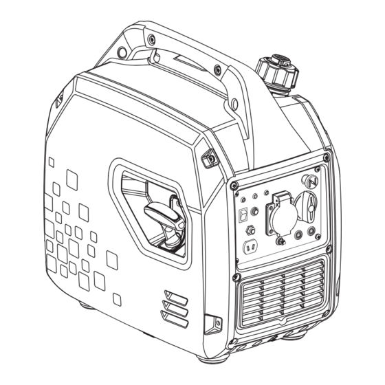
II. FEATURES & CONTROLS 1. Carrying Handle 6. Control Panel 2. Fuel Tank Cap 7. Generator Cover 3. Ventilation Knob 8. Muffler 4. Spark Plug Housing 9. Muffler Blind Window 5. Recoil Start CONTROL PANEL 1. Running Indicator 2. Overload Indicator 3. - Page 7 RUNNING INDICATOR (GREEN) 2. Check the air intake for impurities and check the control parts for any The running indicator lights up when abnormalities - handle immediately if generator starts and has normal necessary. output. 3. Press the re button. OIL ALARM INDICATOR (YELLOW) When the oil level drops below the lower limit, the oil protection system will stop...
- Page 8 ENERGY-SAVING SWITCH TWO-IN-ONE SWITCH (Engine Stop & Fuel Switch) When the energy-saving switch is in “ON” position, the energy saving equipment When the switch is in “OFF” position, it controls the engine rotatation speed indicates that the generator is in stop according to the connected loads.
- Page 9 PARALLEL KIT TERMINAL VENTILATION KNOB It is used for parallel operation with another inverter (parallel kits sold separately). The fuel tank cap is equipped with the ventilation knob to prevent leakage of fuel. The ventilation knob must be in “ON” PUSH-BUTTON START position when operating the generator.
-
Page 10: Operating
III. OPERATING CAUTION Even with carburetor modification, 1. OPERATING ENVIRONMENT generator horsepower will decrease about 3.5% for each 1,000 feet (300 meters) Only use and operate the generator increase in altitude. The effect of altitude outside in well-ventilated spaces. on horsepower will be greater than this if no carburetor modification is made. -
Page 11: Oil Check
3. OIL CHECK Refer to add oil instruction in MAINTENANCE section for more Place the engine on a level surface with information. engine stopped. Check the engine oil level. Remove the oil maintenance cover. Remove the dipstick and wipe it clean. Oil Capacity(Rated}: Reinstall dipstick into hole;... -
Page 12: Fuel Check
CAUTION Fuel capacity (rated): See parameters. Operate generator only on leveled surfaces. The engine is equipped with a NEVER use engine or carburetor cleaner low oil sensor (applicable types) that will products in the fuel tank or permanent automatic stop the engine when the oil damage may occur. -
Page 13: Internal Battery Grounding
5. INTERNAL BATTERY GROUNDING DANGER (Applicable Types). Electrical Shock Remove the appearance cover plate. Use Failure to properly ground the generator the nut of M6 to connect the battery can result in electric shock. grounding wire with cylinder head cover to make the ground connection of internal A ground terminal has been provided battery. -
Page 14: Manual Start
8.4. Turn the energy saving switch to the When starting the engine, grasp the recoil “ON” position. (: Please the starter handle and pull slowly until energy saving switch to “OFF” position resistance is felt. Then pull rapidly to start when it needs large starting current. -
Page 15: Electric Start
If engine is equipped with an engine oil If the starter cannot crank the engine, alarm, it is possible that the engine oil in please release the switch button. Do not the crankcase is lower than the minimum attempt to start the engine again before level required. -
Page 16: Wireless Remote Control
11. WIRELESS REMOTE CONTROL WARNING (If applicable) Do not start or close the generator when the output terminal of the generator is connected to an electric device and the electric device is in “ON” state. 12. CONNECT TO ELECTRICAL DEVICES 1. -
Page 17: Loading Capacity
ELECTRICAL SHOCKS WARNING To reduce the risk of electrical shocks, DO It is necessary to equip with circuit NOT use electrical cords that are worn, protector or switch to isolate the frayed, bare or otherwise damaged. generator from the electric utility when the generator is mainly used for backup. -
Page 18: Stopping The Generator
15. STOPPING THE GENERATOR 3. Turn the energy saving switch to the “ON” position. 1. Remove the connectors of all electric equipment from the generator panel. 4. Allow the generator to run at no load for a few minutes to stabilise internal temperatures of the engine and generator. -
Page 19: Maintenance
During parallel operation, energy-saving IV. MAINTENANCE switches of generators should be in the same position. It is the operator’s responsibility to complete all scheduled maintenance in a 1. Connect one generator to the other timely manner. Correct any issue before generator(s) in parallel. -
Page 20: Maintenance Schedule
1. MAINTENANCE SCHEDULE Stop the generator before servicing. Disconnect all electrical devices and battery (if equipped), and cool down the generator completely before conducting the service. Service the generator in a clean, dry and flat area. Follow the service intervals indicated in the chart below. -
Page 21: Generator Maintenance
2. GENERATOR MAINTENANCE the indicated range. Use a damp cloth to clean exterior surfaces of the generator. Use a soft brush to clean the dirt and oil. Use an compressed air (25 PSI) to clear dirt and debris from the generator. Inspect all air vents and cooling slots to ensure that they are clean and unobstructed. - Page 22 D. Fully tighten the dipstick. E. Dispose of used oil at an approved waste management facility. CAUTION OIL LEVEL CHECK Reinstall dipstick into hole; rest on oil fill neck. DO NOT thread cap into hole. E. Add recommended oil to the upper f.
- Page 23 AIR FILTER WARNING A. Remove the appearance cover. DO NOT run the engine without the air filter, or serious danger can result. B. Loosen the filter fix clamp and remove the cover of the air filter. SPARK PLUG C. Remove the foam filter element. A.
-
Page 24: Storage & Transportation
F. Carefully thread the plug into the engine by hand. G. After the spark plug is seated, use spark plug wrench to tighten the plug. SPARK PLUG TIGHTEN TORQUE: 15-20 N.m H. Attach the spark cap to the plug and connect the spark plug wire to the plug. - Page 25 Unscrew the oil dipstick and slightly tilt WARNING the whole to pour out the oil. Do not overfill the tank. 6. Remove the spark plug and pour about 15 ml of oil into the cylinder. Pull the recoil Do not operate the generator while it is on starter slightly to distribute the oil and or inside a vehicle.
-
Page 26: Troubleshooting
VI. TROUBLESHOOTING... -
Page 27: Specifications
VII. SPECIFICATIONS 1. SPECIFICATION PARAMETER TABLE... - Page 28 VII. SPECIFICATIONS Note: The generator with different specification and configurations may have different parameters and may change at any time without notice.
-
Page 29: Wiring Diagram
VII. SPECIFICATIONS 2. WIRING DIAGRAM RECOIL STARTING... - Page 30 VII. SPECIFICATIONS ELECTRIC STARTING NOTE: Because of the differences in generators, the wiring diagram is only for reference.
-
Page 31: Warranty
In order to be eligible for the LawnMaster at the expense of the owner. All defective limited warranty, you must have,... - Page 32 WARRANTY EXCLUSIONS • Normal phenomena such as noise, vibration and or oil, are considered • Any damage which results from by Steelfort as not affecting the neglect of periodic maintenance quality, function or performance of specified by Steelfort. the product. •...
- Page 33 • Incidental expenses that are piston pins, valve seats, stems and incurred in the warranty claim for bearings. additional expenses such as towing, communications, accommodation • Any damage resulting from exposure and meals, that are incurred due to of the product to soot and smoke, the breakdown of the product at a medicines and chemical agents, remote location are not covered.
- Page 34 Steelfort 500 Rangitikei Street Private Bag 11045 Palmerston North, 4442, New Zealand 06 350 1350 | steelfort.co.nz Steelfort Auckland 880 Great South Road, Penrose SCAN TO VIEW THE Auckland, 1061, New Zealand LAWNMASTER RANGE 09 573 1324 | outlet@steelfort.co.nz steelfortnz...
Need help?
Do you have a question about the BQH2000 and is the answer not in the manual?
Questions and answers