Subscribe to Our Youtube Channel
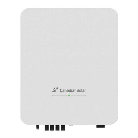
Summary of Contents for CanadianSolar CSI-15K-T4001A-E
- Page 1 CSI-15K-T4001A-E CSI-17K-T4001A-E CSI-20K-T4001A-E CSI-23K-T4001A-E CSI-25K-T4001A-E PV Inverter Quick Installation Guide (Part No: 91000517; Release Date: December, 2023) EN-Rev QI/V02a December, 2023. CSI Solar Co., Ltd.
-
Page 3: About This Guide
1 About This Guide This guide only applies to the following inverters:CSI-15K-T4001A-E,CSI-17K-T4001A-E, CSI-20K-T4001A-E,CSI-23K- T4001A-E, CSI-25K-T4001A-E. This instruction only provides an overview of the installation of the above-mentioned inverters. Due to product version upgrades or other reasons, this guidance will be updated irregularly. Under no circumstances can this guide replace the user manual and the safety instructions on the product. -
Page 4: Installation Environment Requirements
3 Installation 3.1 Installation Environment Requirements 1) Do not install the inverter on structures constructed of flammable, thermolabile, or explosive materials. 2) Ensure the inverter is out of children's reach. 3) The ambient temperature should be between -30℃~ 60℃. 4) The humidity of the installation location should be below 100% without condensation. 5) Do not install the inverter outdoors in salt, sulfur, or other corrosive areas. -
Page 5: Installation Clearance Requirements
3.4 Installation Clearance Requirements FIG 3-3 Single inverter installation clearance 3.5 Inverter Installation Step 1: Use the wall-mounting bracket as a template and mark the positions of the drill holes, then drill the 3 holes (Diameter = 11mm, Depth ≥ 55mm). Step 2: Knock expansion anchors into the corresponding three holes, and then secure the bracket by using screws. - Page 6 Description Specification 15kW / 17 kW / 20 kW:13-22mm A Cable Outer Diameter 23 kW / 25 kW:13~26mm D-5mm 15kW / 17 kW / 20 kW :5x4~16mm Cross Sectional Area of Copper (REC 6mm ) Conductor 23 kW / 25 kW :5x6~16mm (REC 10mm )...
- Page 7 4.2 Connecting the PE Cable Since the inverter is a transformerless inverter, neither the negative pole nor the positive pole of the PV string can be grounded. Otherwise, the inverter will not operate normally. Connect the additional grounding terminal to the protective grounding point before AC cable WARNING connection, PV cable connection, and communication cable connection.
-
Page 8: Communication Cable Connection
4.3 DC Cable Connection Electric shock! The PV array will generate lethal high voltage once exposed to sunlight. Before performing electrical operations, ensure that all cables are uncharged. DANGER Do not turn on the AC circuit breaker before the inverter is electrically connected. Ensure that the DC switch of the inverter is set to OFF. -
Page 9: Dongle Connection
Step 1: Prepare the Signal Cable. Remove the signal cable’s jacket about 23mm, and then strip the wire insulation layer about 7mm, as per figure below. Core wire cross- Outside Type sectional area diameter Shielded type 0.25-1mm 4~5.5mm 2-core twisted pair (24~18AWG) FIG 4-9 Communication cable requirements Step2: Insert the conductors into the corresponding pins of the plug, and then fix the conductors by screws firmly,as shown... - Page 10 5 Commissioning Inverter 5.1 Electrical Inspection 1) The inverter DC switch and external circuit breaker are disconnected 2) The inverter should be accessible for operation, maintenance and service. 3) Nothing is left on the top of the inverter. 4) The inverter is correctly connected to the external devices, and the cables are routed in a safe place or protected against mechanical damage.
- Page 11 6.3 Use the Local Mode to Login the App Notice:To use the local mode, the following conditions should be met: (1) The dongle is connected to the inverter and powered on. (2) The distance between the mobile phone and the dongle should be within 5m and there is no shelter. Make sure the Bluetooth of your phone is turned ON.
- Page 12 Step 3:If it is the first time to boot the inverter, you need to set the Grid Code as required on the boot page Must select the correct gird code where the inverter is installed. If the gird code is not suitable, it may cause the inverter to report a fault error.
-
Page 13: Function List
6.4 Function List 7 Obtaining User Manual Please scan the QR code for more detailed information in user manual. EN-Rev QI/V02a December, 2023. CSI Solar Co., Ltd. 11 / 11...


Need help?
Do you have a question about the CSI-15K-T4001A-E and is the answer not in the manual?
Questions and answers