Table of Contents
Advertisement
Quick Links
Advertisement
Table of Contents

Subscribe to Our Youtube Channel
Related Manuals for Dover OPW 88 Series


Summary of Contents for Dover OPW 88 Series
-
Page 1: Operation Manual Opw Engineered Systems
OPERATIONS MANUAL 88XX SERIES RACK MONITOR REVISED 1/2024... - Page 2 Rack Monitor 88XX Document: Operation Manual Date: January 2024 Version: A.0 subject to change Page 2 of 43 – Operations Manual...
-
Page 3: Disclaimer
Rack Monitor 88XX Document: Operation Manual Date: January 2024 Version: A.0 subject to change Disclaimer This manual provides important safety and technical information of the OPW Rack monitor 88XX-series. It is important that this manual is read and understood completely by the installing technician prior to installation. 88XX is a secondary overfill prevention monitor for protecting loading operations from overfilling. -
Page 4: Warranty
Rack Monitor 88XX Document: Operation Manual Date: January 2024 Version: A.0 subject to change Warranty All parts and products are thoroughly inspected and tested from the time raw material is received at our plant, until the product is completed. We guarantee that all products are free from defects in materials and workmanship for a period of one year from the date of shipment. -
Page 5: Table Of Contents
Rack Monitor 88XX Document: Operation Manual Date: January 2024 Version: A.0 subject to change Table of Contents Operation Manual OPW Engineered Systems Disclaimer Warranty Approvals ................................4 Technical Assistance in the U.S.A......................... 4 Table of Contents Specifications Electrical Specifications Inputs Outputs External environment reminder (see installation manual for details) .............. - Page 6 Rack Monitor 88XX Document: Operation Manual Date: January 2024 Version: A.0 subject to change Example of a Loading Cycle with 5-Wire Sensors....................25 Explanation of Used Icons on the Display ......................25 Faulty Detected Sensors Sensor Detection Firmware Upgrade Event Log Communication Settings Data Communication...
-
Page 7: Specifications
Rack Monitor 88XX Document: Operation Manual Date: January 2024 Version: A.0 subject to change Specifications The Rack Monitor 88XX is a loading rack monitoring system, detects and communicates a pending overfill condition to the loading rack control automation equipment by means of a normally open relay contact. In addition, this non- permissive condition as well as diagnostic information is displayed. -
Page 8: Inputs
Rack Monitor 88XX Document: Operation Manual Date: January 2024 Version: A.0 subject to change Inputs Sensor Terminal J5 Pin 1~ 8 : all EN13922 compliant sensors. : all industry standard format overfill detection sensors . Two-Wire sensor (maximum eight) . Five-Wire sensors (maximum twelve) . -
Page 9: External Environment Reminder (See Installation Manual For Details)
Rack Monitor 88XX Document: Operation Manual Date: January 2024 Version: A.0 subject to change Real Time Clock : precise trimmed Quartz real time clock. : clock is set to Greenwich Mean Time (GMT) SD Ram socket : Primarily used for Update Firmware : Secondarily used for Time stamped data / event logging. -
Page 10: Sensors Types
Rack Monitor 88XX Document: Operation Manual Date: January 2024 Version: A.0 subject to change Sensors Types Two-Wire sensors. Five-Wire sensors. Sensors and Grounding Before continuing describing the functionality of the rack monitor a short explanation of the sensors and ground verification. -
Page 11: Sensors Communication
Rack Monitor 88XX Document: Operation Manual Date: January 2024 Version: A.0 subject to change Sensors Communication 882xE,885xE and 887xE are able to communicate with the latest generation OPW overfill sensors (Civastar) as well as the 3205E Onboard Monitor, 1399TT Truck-tester and Civacommand. The 885xE and 887xE Rack Monitor will communicate via the existing wiring. -
Page 12: Relay Operation
Rack Monitor 88XX Document: Operation Manual Date: January 2024 Version: A.0 subject to change Make sure no vehicle is attached at power-up. Note: The cable and plug connections shall be tested continues if an active storage hanger is used. If all tests are passed the rack monitor is ready for use. The first task of the 88XX Rack Monitor is to ensure proper grounding is established via Pin 9 and pin 10 of the plug socket connection to the tank-truck chassis. - Page 13 Rack Monitor 88XX Document: Operation Manual Date: January 2024 Version: A.0 subject to change The AUX1 relay can be utilized for additional functions. Please contact OPW for possibilities 3. A user selectable (normally open - common - normally closed) AUX2 relay is available for four predefined functions.
-
Page 14: Flash Pattern Table
Rack Monitor 88XX Document: Operation Manual Date: January 2024 Version: A.0 subject to change Figure 2 Monitor indicators react differently if the dipswitch setting (1-6) isn’t set and in the default off position. A LED test will be started after power-up. There should be nothing connected at power-up. - Page 15 Rack Monitor 88XX Document: Operation Manual Date: January 2024 Version: A.0 subject to change This flashing pattern is used to indicate the amount of dry → 500m S → ~2Seconds sensors. E.g. an 11 compartment tank truck is equipped DRY com partm ents with 5-wire sensors.
-
Page 16: Ground Verification
Rack Monitor 88XX Document: Operation Manual Date: January 2024 Version: A.0 subject to change Ground Verification The rack monitor will verify the impedance between pin 9 and 10 (including ground bolt) or if a clamp (model 7720) is used between the two jaws or the two pins of or ground plug Model 7620. Ground verification is set if the impedance is within the set boundaries. -
Page 17: Dipswitch Setting "System
Rack Monitor 88XX Document: Operation Manual Date: January 2024 Version: A.0 subject to change Dipswitch Setting “System” Two switch arrays are placed on the main board. Due to software upgrades not all switch settings are explained in this manual. Underlined = Default Function Remarks Switch 1 Switch 2... -
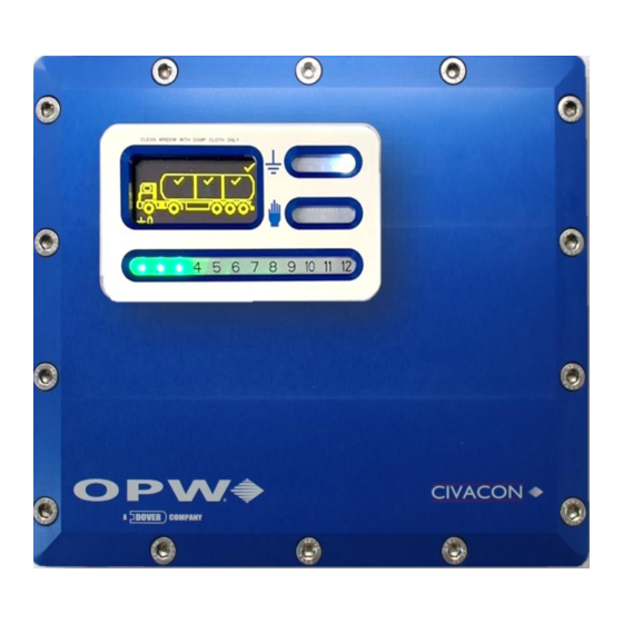
Page 18: Oled Display 88Xx
Rack Monitor 88XX Document: Operation Manual Date: January 2024 Version: A.0 subject to change Oled Display 88XX The 88XX is fitted with an 2,7” Oled display with a temperature range between -45C (-43F) and +70C (158F) 12 multicolor Light Emitting Diode (LED 1~12) indicators are placed in the bottom window to indicate compartment status. -
Page 19: Power-Up
Rack Monitor 88XX Document: Operation Manual Date: January 2024 Version: A.0 subject to change Power-Up The 20 Light Emitting Diodes will be sequentially lit at start up. The software and hardware version are shown on the graphical display as well as Time and Date. In addition, a Config version can be shown. By default the Time (HH:MM:SS) and Date (Day:Month:Year) will be Greenwich Mean Time (see annex C how to set clock). -
Page 20: Function Keys
Rack Monitor 88XX Document: Operation Manual Date: January 2024 Version: A.0 subject to change As soon as the Plug is connected to the truck socket or removed from the active storage hanger the system awakes and is ready for use. If proper ground and dry sensors are detected the rack monitor will switch to permissive. When the loading is finished and the plug is removed from the truck it will wait 15 minutes before it goes back to sleep. -
Page 21: Bypass Operation
Rack Monitor 88XX Document: Operation Manual Date: January 2024 Version: A.0 subject to change Bypass Operation Although it is not recommended, the 88XX can also be bypassed in a faulty or wet sensor condition. If the monitor is NOT set to EN13922 then shorted between channels can be bypassed. Shorted channels to ground cannot be bypassed with the blue key. -
Page 22: Rack Function (Red) Key
Rack Monitor 88XX Document: Operation Manual Date: January 2024 Version: A.0 subject to change down again. This can be done until all sensors are Bypassed. This is of course only possible with 2-Wire sensors. With 5-Wire sensors individual Bypassing of wet sensors is NOT possible. Bypassing can be done for every operational related errors but not for ground verification and for all non-operational errors like shorts, open wires and broken sensors. -
Page 23: Loading
Rack Monitor 88XX Document: Operation Manual Date: January 2024 Version: A.0 subject to change Loading A tank truck with will be shown briefly as soon as the monitor has established type and in case of 5-wire sensors amount of sensors. If 2-wire sensors are connected then the amount of detected compartments are always 8 or 6 (depending on dip switch setting: see Error! Reference source not found. -
Page 24: Example Of A Loading Cycle With 2-Wire Sensors
Rack Monitor 88XX Document: Operation Manual Date: January 2024 Version: A.0 subject to change Example of a Loading Cycle with 2-Wire Sensors NOTE: Symbol (any color) below means flashing Light Emitting Diodes A solid circle means LED indicator are solid on. Icons and compartments can also flash. - Page 25 Rack Monitor 88XX Document: Operation Manual Date: January 2024 Version: A.0 subject to change Example of a Loading Cycle with 5-Wire Sensors Symbol (any color) below means flashing Light Emitting Diodes. A solid circle means LED indicator are solid on Icons and compartments can also flash.
- Page 26 Rack Monitor 88XX Document: Operation Manual Date: January 2024 Version: A.0 subject to change Table 4 Symbol Description Example e.g. Unknown Accepted or valid Rejected or not valid Overfill sensor x-wire Overfill sensor >> 5-wire Overfill sensor Maintenance Unknown overfill Sensor antenna Wi-Fi connections established...
- Page 27 Rack Monitor 88XX Document: Operation Manual Date: January 2024 Version: A.0 subject to change Faulty Detected Sensors LED indication when a sensor fault (or more) is (are) detected Green indicators : all off Red indicator : all correct detected sensors are flashing and faulty sensor(s) is (are) continuous on If the fault is bypassed the rack monitor will revert to the state mentioned above with the faulty channels bypassed.
- Page 28 Rack Monitor 88XX Document: Operation Manual Date: January 2024 Version: A.0 subject to change Step 4 The Rack monitor will apply power to the sensor and analyse the measured signal. If no Two-Wire sensors are detected, power will be applied at channel 8 and a pulse will transmitted at pin 4 If a return pulse is detected the rack monitor will continue with Five-Wire sensors.
- Page 29 Rack Monitor 88XX Document: Operation Manual Date: January 2024 Version: A.0 subject to change Copying files from the card and installing will take approximate 2 minutes. The new firmware will/can be supplied with a new appendix. Please save this appendix with this manual. The rack monitor is ready for use if the screens are flashing in the normal pattern.
- Page 30 Rack Monitor 88XX Document: Operation Manual Date: January 2024 Version: A.0 subject to change Civacon 8500/8800 Protocol Message Format: A1A2* Command_Text Where: = Start of Text = 02 Hex A1A2 = Address = 01-99 Hex Command Text = Character string including Command Code and associated parameters = End of Text = 03 Hex = Longitudinal Redundancy Check...
- Page 31 Rack Monitor 88XX Document: Operation Manual Date: January 2024 Version: A.0 subject to change Table 5 Character ‘C2’ Definition Character 2 Wire 5 Wire 5 Wire Value Sensors Sensors Permit Table 6 Character ‘C3 & C4’ Definition Character Hex Value Sensor 4 Sensor 3 Sensor 2...
- Page 32 Rack Monitor 88XX Document: Operation Manual Date: January 2024 Version: A.0 subject to change Where: = 0 (30 Hex) = No Vehicle Recognition System Detected = 1 (31 Hex) = Vehicle Recognition System Detected = 8 character serial number 6 –Byte Serial code 1-Byte CRC Code 1-Byte Family code Page 32 of 43 –...
- Page 33 Rack Monitor 88XX Document: Operation Manual Date: January 2024 Version: A.0 subject to change Modbus Two register tables are available due compatibility with previous systems. Below is the old and brief defined register table. This information will be available in register 20A to 21A. Reg.
- Page 34 Rack Monitor 88XX Document: Operation Manual Date: January 2024 Version: A.0 subject to change Sensor Status Register 20D ~ 214 State Value Description Unknown Initial State Wet Sensor Dry Sensor Current Modbus 88XX Physical Interface See Error! Reference source not found. Error! Reference source not found. for detailed dipswitch settings Registers Table 5 shows all Modbus registers.
- Page 35 Rack Monitor 88XX Document: Operation Manual Date: January 2024 Version: A.0 subject to change Reset Counts The reset counts keep track of the last reason why the Rack resets and the number of times the rack resets for each reason. Everything is stored as an unsigned 16-bit value. Register Reset reason Last reset reason for reset...
- Page 36 Rack Monitor 88XX Document: Operation Manual Date: January 2024 Version: A.0 subject to change State Value Description Initial value, probe status can’t be determined Initial/Unknown Non permissive No permissive signal from probe permissive Probe is permissive Non permissive latched Probe was non-permissive, but is now permissive Probe doesn’t follow specification Out of spec Open...
- Page 37 Rack Monitor 88XX Document: Operation Manual Date: January 2024 Version: A.0 subject to change State Value Description Initial Initial value Channel good Channel is good Short to ground Channel is shorted to ground Open Channel is open Short to other channel Channel shorted to another channel Channel overloaded Channel is overloaded...
- Page 38 Rack Monitor 88XX Document: Operation Manual Date: January 2024 Version: A.0 subject to change SIL Rating The minimum Sil rating of the 88XX according IEC61508 is SIL1 which means a minimum risk reduction factor of 100.000-1.000.000 per hour at continuous operation. The 88XX can be equipped with a secondary detection circuit with its own relay output to get a higher Sil rating.
- Page 39 Rack Monitor 88XX Document: Operation Manual Date: January 2024 Version: A.0 subject to change Maintenance When servicing the Rack Monitor 88XX, the following needs attention: • Before maintenance the full installation must be shut down/off before proceeding. • Maintenance must be performed by authorized personnel only. •...
- Page 40 Rack Monitor 88XX Document: Operation Manual Date: January 2024 Version: A.0 subject to change Troubleshooting The following troubleshooting guide will give you first aid hands-on in solving most of the problems you can encounter. there are two types of problems: 1.
- Page 41 Rack Monitor 88XX Document: Operation Manual Date: January 2024 Version: A.0 subject to change Condition Possible Cause Solution • The Rack Monitor doesn’t turn ON The mains aren’t connected. Connect the mains. • Check if the main wiring is connected according to the installation instruction.
- Page 42 Rack Monitor 88XX Document: Operation Manual Date: January 2024 Version: A.0 subject to change Annex B – Set Clock The internal real time clock has been calibrated to the highest possible accuracy during production and set to GMT. This clock is mainly used for time stamping the event logging to the SD-Card. The end user might want to set the clock to the local region setting and this can be done in different way’s.
- Page 43 Rack Monitor 88XX Document: Operation Manual Date: January 2024 Version: A.0 subject to change The following parts are also available: Part number Description Quantity EL00203-CRK Internally used connector kit BCU-BLUE Blue Function key (low level) BCU-RED Red Function key (high level) EL06802 SD-Ram Card 8800-BRK-14...
Need help?
Do you have a question about the OPW 88 Series and is the answer not in the manual?
Questions and answers