Table of Contents
Advertisement
Quick Links
INTEGRATED MONITORING SYSTEM
Installation Manual
www.opwglobal.com
Part Number:
M1600, Revision - 7
Central Technical Support Number:
1-877-OPW-TECH (877-679-8324)
Issue
Date: 1/15/20
Calls outside US and Canada:
1-708-485-4200
Fax:
1 (800) 421-3297
Supersedes:
1/9/2015
Hours:
Monday through Friday, 7:00 am to 6:00 pm, US CST
Advertisement
Table of Contents

Subscribe to Our Youtube Channel
Related Manuals for Dover OPW SiteSentinel iSite


Summary of Contents for Dover OPW SiteSentinel iSite
- Page 1 INTEGRATED MONITORING SYSTEM Installation Manual www.opwglobal.com Part Number: M1600, Revision - 7 Central Technical Support Number: 1-877-OPW-TECH (877-679-8324) Issue Date: 1/15/20 Calls outside US and Canada: 1-708-485-4200 Fax: 1 (800) 421-3297 Supersedes: 1/9/2015 Hours: Monday through Friday, 7:00 am to 6:00 pm, US CST...
- Page 2 Page 2 of 145 2013 Delaware Capital Formation, Inc. All Rights Reserved. DOVER and the DOVER logo are registered trademarks of Delaware Capital Formation, Inc., a wholly owned subsidiary of Dover Corporation. OPW Fuel Management Systems' System and Replacement Parts Warranty Statement OPW Fuel Management Systems warrants that all OPW Tank Gauge and Petro Vend Fuel Control systems supplied by OPW Fuel Management Systems to the Original Purchaser will be free from defects in material and/or workmanship under normal use and service for a period of 12 months from the date of installation or 18 months from the date of shipment from OPW.
-
Page 3: Table Of Contents
Page 3 of 145 Table of Contents Contents Before You Begin ............................................10 Installer Safety .............................................. 10 Precision Leak Test ............................................10 Initial Inspection ............................................10 Manifolded Tanks ............................................10 System Overview ............................................11 SiteSentinel® iSite™ Console ........................................11 2.1.1 Blank Door Unit ............................................. - Page 4 Page 4 of 145 Probe Placement ............................................29 Probe Installation in Underground Tanks ..................................... 30 3.2.1 Calculating Product Offset ........................................31 Probe Installation ............................................32 Adaptor Collar & Riser Cap .......................................... 32 Probe Floats ..............................................32 Model 924B Probes ............................................35 Flex Probe Installation ..........................................
- Page 5 Page 5 of 145 5.7.1 Installation ............................................. 46 Discriminating STP Sump Sensor ........................................ 47 5.8.1 Installation ............................................. 47 Hydrocarbon Vapor Sensor .......................................... 48 5.9.1 Installation ............................................. 48 5.10 Discriminating Interstitial Sensor ........................................49 5.10.1 Installation ............................................. 49 5.11 Interstitial Hydrocarbon Liquid Sensor with Water Indicator ................................. 50 5.12 Hydrocarbon Liquid Sensor with Water Indicator ..................................
- Page 6 Page 6 of 145 6.1.2 Installation ............................................. 64 Line Interface Module (LIM) ......................................... 65 7.1.1 Installation Overview..........................................66 Conduit & Cabinet Installation ........................................68 Console Installation ............................................68 VSmart Module Installation .......................................... 69 Line Interface Module (LIM) Installation ....................................... 69 Probe &...
- Page 7 Page 7 of 145 13.1 Prior to Installation ............................................86 13.2 Installation Procedure ........................................... 86 13.2.1 ACR/RIM Hardware Installation ......................................87 13.2.2 ACR/RIM Board Jumper Setup ......................................89 Appendix A: Model 924B Probe Part Numbers ......................................91 Appendix B: Output Relay Installation Report ......................................92 Appendix C: Sensor Labels ............................................
- Page 8 Page 8 of 145 Interstitial Level Sensors ............................................131 Hydrocarbon Liquid Sump Sensor ........................................132 Interstitial Optical Liquid Sensor ........................................... 133 Appendix J: Console Boards ............................................ 134 Appendix K: System Functional Testing ........................................137 Appendix L: Annual Inspection Checklist ........................................140 Declaration of Conformity ............................................
- Page 9 Page 9 of 145 Applicable Warnings The inside of the SiteSentinel→ iSite Console contains no useable parts and operates on high-voltage circuitry; therefore, ONLY certified technicians should be allowed to access the console. However, the internal printer (if installed) may be accessed by the user for regular maintenance including paper replacement.
-
Page 10: Before You Begin
Page 10 of 145 Most regulatory agencies will accept the ATG tank test as the Before You Begin acceptance test on new tank installations. 1.3 Initial Inspection Improper installation may endanger installers and users of this equipment! Read these instructions CAREFULLY. The console Data Sheet, which can be downloaded from the OPW 1.1 Installer Safety Global website at www.opwglobal.com, provides specific details about... -
Page 11: System Overview
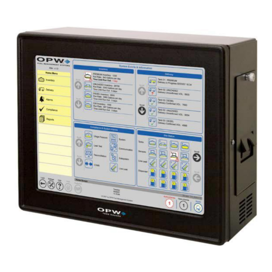
Page 11 of 145 System Overview SiteSentinel® iSite™ Console Specifications 2.1 SiteSentinel® iSite™ Console Width: 15” (38.1 cm) Height: 12” (30.5 cm) Dimensions: The SiteSentinel® iSite™ console (Figure 1-1 SiteSentinel® iSite™ Depth: 7” (17.8 cm) Console) monitors up to 256 probes, 64 AST (Flex) probes, 1,024 sensors or combination of each. -
Page 12: Network Connections
Page 12 of 145 2.2 Network Connections 2.2.1 DHCP and Static IP Connections When a PC logs onto a network, it obtains an Internet Protocol (IP) address in one of two ways by Dynamic Host Configuration Protocol (DHCP) (Figure 2-1 Dynamic Host Configuration Protocol (DHCP)) or by Static IP (Figure 2-2). -
Page 13: Direct Connections
Page 13 of 145 2.2.2 Direct Connections To establish a direct, wired connection between the SiteSentinel® iSite™ Console and a PC, a CAT5 crossover cable is required. Follow these steps to connect: 1. Connect one end of the CAT5 crossover cable to the console’s Ethernet port, and the other end to an available Ethernet port on the PC. -
Page 14: Peripheral Connections
Page 14 of 145 2.3 Peripheral Connections 2.3.2 Wireless Connections Wireless connections can also be used for communications between the 2.3.1 Petro-Net™ Connections VSmart Module and the SiteSentinel® iSite™ console. For this type of Wired RS-485 Petro-Net™ connections can be used for communications connection, a wireless modem is connected to the VSmart Module, and a second modem is wired to the console’s RS-485 port. - Page 15 Page 15 of 145 Figure 2-4 Console Connectivity www.opwglobal.com...
- Page 16 Page 16 of 145 Antenna Ethernet Modem Ports USB Ports Serial Ports Port Ports Figure 2-5 Port Connections www.opwglobal.com...
- Page 17 Page 17 of 145 Figure 2-6 Wiring Connections www.opwglobal.com...
-
Page 18: The Vsmart Module
Page 18 of 145 Up to eight (8) VSmart Modules can be connected to the SiteSentinel® 2.4 The VSmart Module iSite™ console via Petro-Net™ (twisted pair), Ethernet, or wireless connections for a total of 1,024 devices per system. The VSmart Module is where all monitored devices (probes, sensors, and line-leak detectors) are physically connected to the system through Intrinsically Safe (IS) barriers. - Page 19 Page 19 of 145 VSmart Module Specifications Width: 11.3” (28.7 cm) Height: 5.6” (14.2 cm) Dimensions: Depth: 5.8” (14.7 cm) Standard Voltage Supply: 105 to 265 VAC, 50-60 Hz Power Consumption: 60 watts maximum Figure 2-8 VSmart Module (Internal) Temperature Range: -40F to 158F (-40°C to 70°C) For site upgrades from an earlier version of a onsole in which the...
-
Page 20: Vsmart Module Connections
Page 20 of 145 2.4.2 VSmart & I/O Module AC Wiring 2.4.1 VSmart Module Connections 1. Pull two AC power wires from the circuit breaker to each You must remove the Intrinsically Safe barrier panel to attach wiring. module; you may “daisy chain” the wires from module to VSmart power must be off while connecting wires! Connect the probe module, not to exceed the circuit-breaker rating (see Figure 2-9). - Page 21 Page 21 of 145 Figure 2-10 Petro-Net and A/C Wiring To maintain intrinsic safety, a separate and completely independent ground connection MUST be run from the I.S. GND terminal on each VSmart Module directly back to the main panel. www.opwglobal.com...
- Page 22 Page 22 of 145 Figure 2-11 Standard Twisted-Pair Petro-Net Installation www.opwglobal.com...
- Page 23 Page 23 of 145 Note 2 It is highly recommended that all wireless Petro-Net installations are subjected to a site survey prior to installation to identify potential interference problems. Figure 2-12 Wireless Petro-Net with VSmart in a Building www.opwglobal.com...
- Page 24 Page 24 of 145 Note 2 It is highly recommended that all wireless Petro-Net installations are subjected to a site survey prior to installation to identify potential interference problems. Figure 2-13 Wireless Petro-Net with VSmart Pole-Mounted Outside www.opwglobal.com...
- Page 25 Page 25 of 145 Figure 2-14 Petro-Net Over Ethernet Option www.opwglobal.com...
-
Page 26: Tank Alert Modules
Page 26 of 145 2.5 Tank Alert Modules The SiteSentinel® iSite™ console has the ability to trigger an overfill alarm using the Tank Alert module (Figure 2-16). This module has an audible buzzer and an external light to warn the users in an event of overfill or high-product alarm. - Page 27 Page 27 of 145 Figure 2-17 Petro-Net Conduit Installation Wireless or Ethernet connections can be substituted during Petro-Net™ installation. www.opwglobal.com...
-
Page 28: Internal Printer
Page 28 of 145 2.6 Internal Printer An internal thermal printer option is available for the SiteSentinel® iSite™ Console. The printer will install inside the cabinet. The printer will be used for printing the various reports the SiteSentinel® iSite™ has available. -
Page 29: Tank Preparation
Page 29 of 145 Tank Preparation 3.1 Probe Placement The ideal location for a probe is in the center of the tank (Figure 3-1). The probe should be located at least 3 feet (91.4 cm) from the tank fill pipe. If this distance is less than 3 feet (91.4 cm), the force of the product entering the tank can cause the water float to rise up the shaft of the probe. -
Page 30: Probe Installation In Underground Tanks
Page 30 of 145 3.2 Probe Installation in Underground Tanks 1. Refer to Figure 3-2. Install a manhole of at least 18 inches (45.7 cm) diameter around an unused fitting in the top of the tank. This manhole must be large enough to accommodate a weatherproof junction box. -
Page 31: Calculating Product Offset
Page 31 of 145 3.2.1 Calculating Product Offset You can calculate product offset for a probe that is not installed in the center of a "pitched" tank. Pitch is the tilt of a tank along its horizontal axis. Some tanks are intentionally installed with one end lower than the other to allow water and sediment to collect at the low end, while clear product is drawn from the high end. -
Page 32: Probe Installation
Page 32 of 145 Probe Installation Probe Floats 4.1 Adaptor Collar & Riser Cap Probe Type/Float Style: Float Kits A modified adaptor collar and riser cap is required for each probe. These Gas: 30-1508-02 collar and riser cap kits are available from OPW Fuel Management 924 and 924B 4”... - Page 33 Page 33 of 145 www.opwglobal.com...
- Page 34 Page 34 of 145 Figure 4-1 924B Probe Installation www.opwglobal.com...
-
Page 35: Model 924B Probes
Page 35 of 145 4.3 Model 924B Probes Model 924B Probe Specifications The 924B Probe (Figure 4-2) is OPW’s latest probe model. This probe comes standard in stainless steel and can be used in a variety of Power Requirements: Nominal 12+ VDC from VSmart I.S. Module liquids, including gasoline, diesel and water. - Page 36 Page 36 of 145 The 7100V Flex Probe (Figure 4-3) utilizes the same magnetostrictive Model 7100V Flex Probe technology for above ground tanks up to 50 feet (15.2 m) in height. It is important to follow the handling instructions to avoid damaging the probe and voiding the warranty.
-
Page 37: Flex Probe Installation
Page 37 of 145 4.5 Flex Probe Installation 4.5.2 Installation Preparations Proper operation of the SiteSentinel® iSite™ system using the flex Measure the product level in the tank. Keep tank out of probe depends on the correct sizing of the probe. If the probe is too service to prevent product level from changing. -
Page 38: Installing Adaptor, Float, Weight On The Probe
Page 38 of 145 4.5.4 Installing Adaptor, Float, Weight on the Probe 4.5.5 Installing the Flex Probe 12. Carry the probe to the top of the tank in its rolled-up state. 19. Position the coiled probe over your shoulder so that the coil 13. -
Page 39: Finishing The Flex Probe Installation
Page 39 of 145 4.5.6 Finishing the Flex Probe Installation 25. Connect the probe wiring bushing ½-inch NPT to the junction box using a short length [18 inches (45.7 cm) max] of flex conduit. 26. Connect the probe to the cable in the junction box and console as below. -
Page 40: Flex Probe Specifications
Page 40 of 145 4.5.7 Flex Probe Specifications Dead Zone Multiple RTD Thermistor Location Overall Length Dead Band Clearance Probe Type Overall Probe Length Thermistor Location 51”-144” (130-366 cm) 6” (15.2 cm) 1” (2.5 cm) Shorter than 144” (366 cm) (Temp Span +7”... -
Page 41: Sensors
Page 41 of 145 Sensors The new smart sensors have the ability to monitor all contained areas of the fuel-storage system: tank interstice, piping sumps, STP containment sumps, dispenser sumps/pans and monitoring wells. Sensors connected to the VSmart Module are automatically detected and identified by the console. -
Page 42: Interstitial Level Sensor Float Switch
Page 42 of 145 This technology allows the SiteSentinel® iSite™ and VSmart Module to 5.3 Interstitial Level Sensor Float Switch automatically detect sensor connection, sensor type and sensor status, Part No. 30-0231-S will minimize user entry error and identify hardware issues with minimal troubleshooting. -
Page 43: Single-Level Sump Sensor
Page 43 of 145 Maximum Wiring Length is the maximum length of cable to be used to 5.4 Single-Level Sump Sensor connect all sensors on an individual channel. This length includes run Part No. 30-0231-L of cable from VSmart to each sensor board in the string. The Single-Level Sump Sensor (Figure 5-4) is designed to detect the 5.4.1 Installation presence of liquid in sumps, dispenser pans and other locations where... -
Page 44: Universal Sump Sensor
Page 44 of 145 5.5 Universal Sump Sensor The Universal Sump Sensor (Figure 5-5) is used in an attached manway riser, double-wall piping, or an attached collar riser. A sump sensor detects the presence of any liquid in a piping sump. When enough liquid enters the sump riser, it activates the sump sensor. -
Page 45: Liquid-Only Float Sensor
Page 45 of 145 5.6 Liquid-Only Float Sensor *Maximum Wiring Length is the maximum length of cable to be used to connect all sensors on an individual channel. This length includes Part No. 30-0230-S run of cable from VSmart to each sensor board in the string. Designed to detect the presence of fluid in the interstitial space of a steel 5.6.1 Installation double-walled tank or a containment sump. -
Page 46: Discriminating Dispenser Pan Sensor
Page 46 of 145 5.7 Discriminating Dispenser Pan Sensor *Maximum Wiring Length is the maximum length of cable to be used Part No. 30-0232-DH-10 to connect all sensors on an individual channel. This length includes The Discriminating Dispenser Pan Sensor (Figure 5-7) detects run of cable from VSmart to each sensor board in the string. -
Page 47: Discriminating Stp Sump Sensor
Page 47 of 145 *Maximum Wiring Length is the maximum length of cable to be used 5.8 Discriminating STP Sump Sensor to connect all sensors on an individual channel. This length includes Part No. 30-0232-DH-20 run of cable from VSmart to each sensor board in the string. The Discriminating STP Sump Sensor (Figure 5-8) detects abnormally 5.8.1 Installation high or low liquid levels and distinguishes liquid type (water or... -
Page 48: Hydrocarbon Vapor Sensor
Page 48 of 145 5.9 Hydrocarbon Vapor Sensor Depending on saturation factor, the sensor may require up to 30 minutes to return to normal after vapors have dissipated. Part No. 30-0235-V *Maximum Wiring Length is the maximum length of cable to be used The Hydrocarbon Vapor Sensor (Figure 5-9) detects hydrocarbon to connect all sensors on an individual channel. -
Page 49: Discriminating Interstitial Sensor
Page 49 of 145 *Maximum Wiring Length is the maximum length of cable to be used 5.10 Discriminating Interstitial Sensor to connect all sensors on an individual channel. This length includes Part No. 30-0236-LW run of cable from VSmart to each sensor board in the string. The Discriminating Interstitial Sensor (Figure 5-10) utilizes a solid-state 5.10.1 Installation optical technology to detect the presence of fluid in the annular space of... -
Page 50: Interstitial Hydrocarbon Liquid Sensor With Water Indicator
Page 50 of 145 *Maximum Wiring Length is the maximum length of cable to be used 5.11 Interstitial Hydrocarbon Liquid Sensor with to connect all sensors on an individual channel. This length includes Water Indicator run of cable from VSmart to each sensor board in the string. Part No. -
Page 51: Hydrocarbon Liquid Sensor With Water Indicator
Page 51 of 145 5.12 Hydrocarbon Liquid Sensor with Water Hydrocarbon Liquid/Water Sensor Specifications Indicator Part Nos.: 6 feet: 30-0234-HW-06; 15 feet: 30-0234-HW-15; Primary Use(s): Monitoring wells 20 feet: 30-0234-HW-20 Detects: Liquid hydrocarbons and water The Hydrocarbon Liquid/Water Sensor (Figure 5-12), which is available in lengths of 6 feet (1.8 m), 15 feet (4.6 m) and 20 feet (6.1 Operating Temperature: -40°F to 158°F (-40°C to +70°C) -
Page 52: Interstitial Sensor
Page 52 of 145 5.13 Interstitial Sensor Interstitial Sensors can be installed around the inside perimeter of the retaining wall or “snaked” under the length of an above ground storage tank within the retaining wall area (Figure 5-13 and Figure 5-14). Interstitial Sensors can also be installed in manways (Figure 5-14), in trenches or inside a sump. -
Page 53: Dual-Float Dispenser Sump Sensor
Page 53 of 145 5.14 Dual-Float Dispenser Sump Sensor Maximum Wiring Length is the maximum length of cable to be used to connect all sensors on an individual channel. This length includes Part No. 30-0232-D-10 run of cable from VSmart to each sensor board in the string. This Dual-Float Sensor is the same as a Discriminating Dispenser Pan ®... -
Page 54: Dual-Float Stp Sump Sensor
Page 54 of 145 Maximum Wiring Length is the maximum length of cable to be used 5.15 Dual-Float STP Sump Sensor to connect all sensors on an individual channel. This length includes Part No. 30-0232-D-20 run of cable from VSmart to each sensor board in the string. This Dual-Float Sensor is the same as a Discriminating STP Sump ®... -
Page 55: Dual-Float Brine Sensors
Page 55 of 145 Maximum Wiring Length is the maximum length of cable to be used 5.16 Dual-Float Brine Sensors to connect all sensors on an individual channel. This length includes run of cable from VSmart to each sensor board in the string. 5.16.1 Dual-Float Brine Sensor (D-10) Part No. -
Page 56: Dual-Float Brine Sensor (D-20B)
Page 56 of 145 Maximum Wiring Length is the maximum length of cable to be used 5.16.2 Dual-Float Brine Sensor (D-20B) to connect all sensors on an individual channel. This length includes run of cable from VSmart to each sensor board in the string. Part No. -
Page 57: Reservoir Sensor Installation
Page 57 of 145 5.17 Reservoir Sensor Installation Use a Universal Reservoir Sensor with hydrostatically monitored tanks. The Reservoir Sensor monitors the level of the liquid in the reservoir of a double-walled tank (Figure 5-19). The sensor has a single float that detects abnormally high or low liquid levels within the reservoir. -
Page 58: Density Measurement Sensor (Dms)
Page 58 of 145 5.18 Density Measurement Sensor (DMS) Part No. 30-3232 The Density Measurement Sensor (DMS) (Figure 5-20) installs on the pre-existing probe and continuously measures the average density of the fuel in the tank. This provides a measure of even the smallest change in product density within the API density range. -
Page 59: Dms Installation
Page 59 of 145 “Density Probe” option to be flagged in the Section of “Integrated 5.18.1 DMS Installation Density Sensor,” which is shown below. For density probes, three As density sensing is no longer an option in the system, the sensor density sensors are allowed. - Page 60 Page 60 of 145 12. To check current density readings from the system, click “Verify Density Device.” The system will start calculating the density readings and then display the information in the window for verification, as shown below: Figure 5-21 Current Density Values www.opwglobal.com...
- Page 61 Page 61 of 145 Figure 5-22 In-Tank Probe Setup www.opwglobal.com...
-
Page 62: Tank Thresholds
Page 62 of 145 3. Click “Verify Density Device Values,” take the difference of 5.18.3 Tank Thresholds the density results from steps 19 and 20 (Density from step 19 minus the density from step 20). 1. As the Density Sensor is installed between the water and 4. -
Page 63: Leak Detection
Page 63 of 145 *Maximum Wiring Length is the maximum length of cable to be used Leak Detection to connect all sensors on an individual channel. The length includes run of cable from VSmart to each sensor board in the string. 6.1 Volumetric Line Leak Detector (VLLD) Sensor Part No. -
Page 64: Installation
Page 64 of 145 6.1.2 Installation Remove all pressure from the product piping. 2. Remove the current mechanical leak detector. CAUTION: Be sure to prevent any debris or scaling from entering system through the leak detector opening. 3. Use the fuel-absorbent cloths to soak up fuel within the work area and around the dry pipe threads. -
Page 65: Line Interface Module (Lim)
Page 65 of 145 Line Interface Module (LIM) The LIM device is a magnetic contactor that supplies line/tank activity Line Leak Interface Module by monitoring input/output status of nozzle signals and Submersible Turbine Pump (STP) contactors. Monitors: Nozzle Signal and STP Contactors Each Line Interface Module (LIM) interface (maximum of four (4) per system) will monitor up to four (4) pressurized lines (for a total of 16 6”... -
Page 66: Installation Overview
Page 66 of 145 7.1.1 Installation Overview Installation vary depending your submersible pump manufacturer; therefore, installation overview may vary from site to site. Figure 7-2 LIM System Overview Typical FE Petro Connection Figure 7-2 Variable Speed Control Wiring for FE Petro Figure 7-4 Typical FE Petro Wiring Connections www.opwglobal.com... - Page 67 Page 67 of 145 Typical Red Jacket Connection Figure 7-6 Typical Red Jacket Wiring Connections Figure 7-5 Variable Speed Control Wiring for Red Jacket www.opwglobal.com...
-
Page 68: Conduit & Cabinet Installation
Page 68 of 145 Conduit & Cabinet Installation 8.1 Console Installation Mount the SiteSentinel® iSite™ console on a wall in a secure indoor location using the mounting holes provided, or use the rubber feet included and place on any flat surface for easy access. If possible, align the console so the display is easily visible and at a comfortable eye level (approximately 5 to 6 feet (1.5 to 1.9 m) above ground if mounted on a wall). -
Page 69: Vsmart Module Installation
Page 69 of 145 8.3 Line Interface Module (LIM) Installation 8.2 VSmart Module Installation The Line Interface Module must be mounted on a wall using ONLY the The VSmart Modules must be mounted on a wall using ONLY the mounting tabs provided. Knockout locations are shown below. LIMs mounting tabs provided. -
Page 70: Probe & Sensor Conduits
Page 70 of 145 8.4.2 RS-232 Communications Conduits 8.4 Probe & Sensor Conduits If a terminal or PC located more than 6 feet (1.8 m) from the console is All installations must be carried out in accordance with local regulations. to be connected, conduit must be installed to accommodate the RS- Rigid steel conduit, which may or may not be required, should be used 232 cable. -
Page 71: I/O Device Conduits
Page 71 of 145 To prevent interference, all wiring to and from the VSmart Module must 8.5 I/O Device Conduits be protected by rigid steel conduit. Probe and sensor wires must be Rigid steel conduit should be used for wiring runs to all I/O devices, alone in their conduits. -
Page 72: Sensor Installation
Page 72 of 145 Due to the variety of surface and soil conditions, a person familiar with Sensor Installation local conditions and codes should determine the placement of monitoring wells. For best results, a groundwater survey should also 9.1 Introduction be completed. -
Page 73: Dry-Well Monitoring, Single-Wall Tank
Page 73 of 145 9.2 Dry-Well Monitoring, Single-Wall Tank Error! Reference source not found. represents a typical dry-well monitoring layout for a single-wall tank. Monitoring wells are placed around the perimeter of the tanks, and are dug as close as possible to the tanks or product lines for optimal sensor response. - Page 74 Page 74 of 145 Figure 9-3 Dry-Well Monitoring, Single-Wall Tank www.opwglobal.com...
-
Page 75: Wet-Well Monitoring, Single-Wall Tank
Page 75 of 145 9.3 Wet-Well Monitoring, Single-Wall Tank Error! Reference source not found. shows a typical wet-monitoring ell layout for a single-wall tank. The sensors are placed around the perimeter of the tanks. The monitoring wells are dug as close as possible to the tanks or product lines for optimal sensor response. -
Page 76: Well Monitoring, Double-Wall Tank
Page 76 of 145 9.4 No-Well Monitoring, Double-Wall Tank The space between the walls of a double-wall tank is the interstitial space, and it is an ideal location for liquid sensors. If the outside tank wall develops a leak, groundwater enters the interstitial space liquid... -
Page 77: Double-Wall Tank With Well Monitoring
Page 77 of 145 9.5 Double-Wall Tank with Well Monitoring A monitoring well is used with a double-wall tank only if the local water table reaches tank level. Because of the danger of water-table contamination, install the well with a Liquid Phase Sensor. Error! Reference source not found. - Page 78 Page 78 of 145 Figure 9-7 Double-Wall Tank with Well Monitoring www.opwglobal.com...
-
Page 79: Probe-Cable Seal-Offs
Page 79 of 145 10 Probe-Cable Seal-Offs Seal-off probe cables before they enter the VSmart Module! This prevents explosive vapors from entering the module. Remove enough of the jacket to allow approximately 3 inches (7.6 cm) of wire leads to extend past each seal-off. -
Page 80: Other System Parameters
Page 80 of 145 Follow these steps to set the Petro-Net™ Address: 11 Other System Parameters Turn the module power OFF. 11.1 VSmart Module Petro-Net™ Addressing 2. Use a ¼-inch (6 mm) blade screwdriver to gently rotate the small white screw inside the rotary switch to the VSmart Modules and I/O Modules must each be assigned a unique desired location. -
Page 81: Installation With Existing Opw/Eeco Equipment
Page 81 of 145 Five temperature sensors reside in the probe shaft for measuring 12 Installation with Existing OPW/EECO product temperature at different levels in the tank. They are located at positions of approximately 20%, 40%, 60% and 80% of the tank’s Equipment volume. -
Page 82: Model Eeco Probes
Page 82 of 145 Five temperature sensors reside in the probe shaft for measuring 12.2 Model EECO Probes product temperature at different levels in the tank. They are located at positions of approximately 20%, 40%, 60% and 80% of the tank’s CANNOT BE MULTI-DROPPED ON VSmart. -
Page 83: Sitesentinel® Isite™ Smart Module
Page 83 of 145 12.3 SiteSentinel® iSite™ Smart Module Smart Module Specifications The Smart Module gathers probe and sensor data. Up to four devices Electrical Requirements can be connected to the Intrinsically Safe (I.S.) barrier in the Smart Standard Voltage Supply: 105 to 125 VAC, 60 Hz Module. -
Page 84: Waterproof Field Electrical Connections
Page 84 of 145 12.4 Waterproof Field Electrical Connections It is VERY important to seal all probe and sensor connections in the junction box to prevent corrosion of the wires. Twist bare ends of wires together. Secure the connection with a wire nut. DO NOT use electrical tape on any connections! Tape prevents proper sealing of the epoxy. -
Page 85: Acr/Rim
Page 85 of 145 13 ACR/RIM The ACR/RIM collects pump transaction data from electronic pumps to provide the OPW tank gauges required data for auto-recalibration and reconcile transactions against tank inventories. • ACR - Automatic Calibration and Reconciliation • RIM - Reconciliation Interface Module Due to the flexibility of the system and the unique nature of every site, it is not possible to show every possible installation scenario. -
Page 86: Prior To Installation
Page 86 of 145 13.2 Installation Procedure 13.1 Prior to Installation All dispensers and controller are installed according to manufacturer’s Check the following: specifications and should be tested for proper operation. 1. Enclosure Mounting: OPW Tank Gauge is installed to specifications Knockouts and mounting means are provided for all cabinetry. -
Page 87: Acr/Rim Hardware Installation
Page 87 of 145 3. Mount the ACR/RIM board on the left-side stand-offs in the 13.2.1 ACR/RIM Hardware Installation enclosure. Installing ACR/RIM Interface: Attach the enclosure to a wall with fasteners (not-supplied) within 5 feet (1.5 m) of the SiteSentinel® iSite™ controller. Enclosure needs to be in a non-hazardous location. - Page 88 Page 88 of 145 5. Locate Wayne Distribution box and wire from CN9 connector to an unused pump position in the D-Box. • Set Jumpers on RIM interface for Wayne • Locate Wayne/Dresser distribution box and wire the other end into an unused pump position in the D-Box. In the event that the D-Box board is full, wire in “series”...
-
Page 89: Acr/Rim Board Jumper Setup
Page 89 of 145 13.2.2 ACR/RIM Board Jumper Setup Jumper # Pins Function Pump Type Setup jumpers to match pump type being connected. When a jumper is set as ON, this means the jumper will tie both pins Gilbarco Wayne together. - Page 90 Page 90 of 145 Figure 13-7 ACR/RIM Jumper Board www.opwglobal.com...
-
Page 91: Appendix A: Model 924B Probe Part Numbers
Page 91 of 145 Appendix A: Model 924B Probe Part Numbers Model 924B Probe Part Numbers Probe Length Length (cm) Part Number 53” Probe for 4’ (122 cm) Diameter/Height Tank 134.6 cm 30-B053 69” Probe for 5’ (152 cm) Diameter/Height Double-Wall Tank 175.3 cm 30-B069 77”... -
Page 92: Appendix B: Output Relay Installation Report
Page 92 of 145 Appendix B: Output Relay Installation Report Output Relay Installation Records Output Location: Output Controls: Normally Open/Normally Closed I/O Module Number (Internal/External OM4) (External Alarm, Dispenser etc.) SiteSentinel® iSite™ Internal Relay Output 1 SiteSentinel® iSite™ Internal Relay Output 2 External Output 1 Position 1 External Output 1 Position 2 External Output 1 Position 3... - Page 93 Page 93 of 145 Appendix B (cont.) Output Relay Installation Records Output Location Output Controls: Normally Open/Normally Closed I/O Module Number (Internal/External OM4) (External Alarm, Dispenser etc.) External Output 3 Position 3 External Output 3 Position 4 External Output 4 Position 1 External Output 4 Position 2 External Output 4 Position 3 External Output 4 Position 4...
-
Page 94: Appendix C: Sensor Labels
Page 94 of 145 Appendix C: Sensor Labels Installed Sensor Labels Description (Location, e.g. Sump, Sensor #) Place Label Here Place Label Here www.opwglobal.com... - Page 95 Page 95 of 145 Appendix C (continued) Installed Sensor Labels Description (Location, e.g. Sump, Sensor #) Place Label Here Place Label Here www.opwglobal.com...
-
Page 96: Appendix D: 7100V Flex Probe Installation Records
Page 96 of 145 Appendix D: 7100V Flex Probe Installation Records 7100V Flex Probe Installation Records Probe Serial Number Probe Part Number (Catalog #) Tank # Product in Tank VSmart Module Number 1–8 Barrier Position 0–3 www.opwglobal.com... - Page 97 Page 97 of 145 Appendix D (continued) 7100V Flex Probe Installation Records Probe Serial Number Probe Part Number (Catalog #) Tank # Product in Tank VSmart Module Number 1–8 Barrier Position 0–3 www.opwglobal.com...
-
Page 98: Appendix E: Model 924B Probe Installation Records
Page 98 of 145 Appendix E: Model 924B Probe Installation Records Model 924 Probe Installation Records Probe Serial Number Tank Number Product in Tank VSmart Module Number (1-8) Barrier Position (1-4) (Number in chain, if applicable, 1-4) www.opwglobal.com... - Page 99 Page 99 of 145 Appendix E (continued) Model 924 Probe Installation Records Probe Serial Number Tank Number Product in Tank VSmart Module Number (1-8) Barrier Position (1-4) (Number in chain, if applicable, 1-4) www.opwglobal.com...
-
Page 100: Appendix F: Icon Glossary
Page 100 of 145 Appendix F: Icon Glossary Sensor Alarms in the Alarm Calendar Alarm Ended But Alarm Condition Description Normal Alarm Acknowledged Unavailable Ended Acknowledged Part numbers and description that would be Icon only seen during Icon outlined with Icon outlined in Icon outlined in Icon completely... - Page 101 Page 101 of 145 Appendix F – Icon Glossary (cont.) Sensor Alarms in the Alarm Calendar Alarm Ended But Alarm Condition Description Normal Alarm Acknowledged Unavailable Not Acknowledged Ended Icon outlined in blue Icon completely Icon outlined with a Icon outlined in blue and triangle is blue.
- Page 102 Page 102 of 145 Appendix F- Icon Glossary (cont.) Sensor Alarms in the Alarm Calendar Alarm Ended But Alarm Condition Description Normal Alarm Acknowledged Unavailable Not Acknowledged Ended Icon outlined in blue Icon completely gray. Displayed when Icon outlined with a Icon outlined in blue Icon only seen and triangle is blue.
- Page 103 Page 103 of 145 Appendix F- Icon Glossary (cont.) Sensor Alarms in the Alarm Calendar Alarm Ended But Alarm Condition Description Normal Alarm Acknowledged Unavailable Not Acknowledged Ended Icon only seen during Icon outlined with a Icon outlined in blue Icon outlined in blue Icon completely gray.
- Page 104 Page 104 of 145 Appendix F- Icon Glossary (cont.) Sensor Alarms in the Alarm Calendar Alarm Ended But Alarm Condition Description Normal Alarm Acknowledged Unavailable Not Acknowledged Ended Icon outlined in blue Icon completely Icon outlined with a Icon outlined in blue and triangle is blue.
- Page 105 Page 105 of 145 Appendix F - Icon Glossary (cont.) Sensor Alarms in the Alarm Calendar Alarm Ended But Alarm Condition Description Normal Alarm Acknowledged Unavailable Not Acknowledged Ended Icon outlined in blue Icon completely gray. Icon outlined with a Icon outlined in blue Icon only seen during and triangle is blue.
- Page 106 Page 106 of 145 Appendix F- Icon Glossary (cont.) Sensor Alarms in the Alarm Calendar Alarm Ended But Alarm Condition Description Normal Alarm Acknowledged Unavailable Not Acknowledged Ended Icon outlined in blue Icon completely gray. Icon outlined with a Icon outlined in blue Icon only seen during and triangle is blue.
- Page 107 Page 107 of 145 Appendix F- Icon Glossary (cont.) Sensor Alarms in the Alarm Calendar Alarm Ended But Alarm Condition Description Normal Alarm Acknowledged Unavailable Not Acknowledged Ended Icon outlined in blue Icon completely gray. Icon outlined with a Icon outlined in blue Icon only seen during and triangle is blue.
- Page 108 Page 108 of 145 Appendix F- Icon Glossary (cont.) Probe/Tank Alarms Alarm Ended But Alarm Condition Description Normal Alarm Acknowledged Unavailable Not Acknowledged Ended Icon outlined in blue Icon completely gray. Icon outlined with a Icon outlined in blue Icon only seen during and triangle is blue.
- Page 109 Page 109 of 145 Appendix F- Icon Glossary (cont.) Probe/Tank Alarms Alarm Ended But Alarm Condition Description Normal Alarm Acknowledged Unavailable Ended Not Acknowledged Icon outlined in blue Icon completely Icon outlined with a Icon outlined in blue Icon only seen and triangle is blue.
- Page 110 Page 110 of 145 Appendix F- Icon Glossary (cont.) Probe/Tank Alarms Alarm Ended But Alarm Condition Description Normal Alarm Acknowledged Unavailable Not Acknowledged Ended Icon outlined in blue Icon completely Icon outlined with a Icon outlined in blue Icon only seen and triangle is blue.
- Page 111 Page 111 of 145 Appendix F- Icon Glossary (cont.) Probe/Tank Alarms Alarm Ended But Alarm Condition Description Normal Alarm Acknowledged Unavailable Ended Not Acknowledged Icon outlined in blue Icon completely gray. Icon outlined with a Icon outlined in blue Icon only seen during and triangle is blue.
- Page 112 Page 112 of 145 Appendix F- Icon Glossary (cont.) Probe/Tank Alarms Alarm Ended But Alarm Condition Description Normal Alarm Acknowledged Unavailable Not Acknowledged Ended Icon outlined in blue Icon completely gray. Icon outlined with a Icon outlined in blue Icon only seen during and triangle is blue.
- Page 113 Page 113 of 145 Appendix F- Icon Glossary (cont.) System Alarms Alarm Ended But Alarm Condition Description Normal Alarm Acknowledged Unavailable Not Acknowledged Ended Icon outlined in blue Icon completely gray. Icon outlined with a Icon outlined in blue Icon only seen during and triangle is blue.
- Page 114 Page 114 of 145 Appendix F- Icon Glossary (cont.) System Alarms Alarm Ended But Alarm Condition Description Normal Alarm Acknowledged Unavailable Not Acknowledged Ended Icon outlined in blue Icon completely gray. Icon outlined with a Icon outlined in blue Icon only seen during and triangle is blue.
- Page 115 Page 115 of 145 Appendix F- Icon Glossary (cont.) Communication Ports Port Available Unavailable Icon Available Unavailable Displayed when the port is Displayed when the item is Displayed when the port is Displayed when the item is available for selection. Icon currently unavailable.
- Page 116 Page 116 of 145 Appendix F- Icon Glossary (cont.) Miscellaneous Icons Icon Available Unavailable Icon Available Unavailable Displayed when the port is Displayed when the item is Displayed when the port is Displayed when the item is available for selection. Icon currently unavailable.
- Page 117 Page 117 of 145 Appendix F- Icon Glossary (cont.) Miscellaneous Icons Icon Available Unavailable Icon Available Unavailable Displayed when the port is Displayed when the item is Displayed when the port is Displayed when the item is available for selection. Icon currently unavailable.
- Page 118 Page 118 of 145 Appendix F- Icon Glossary (cont.) Miscellaneous Icons Alarm Ended But Not Description Normal Alarm Acknowledged Alarm Condition Ended Acknowledged Device icon in normal state. Part numbers and Icon outlined with a dotted Icon outlined in blue with red Icon outlined in blue and Icon completely gray.
- Page 119 Page 119 of 145 Appendix F- Icon Glossary (cont.) Miscellaneous Icons Alarm Ended But Not Description Normal Alarm Acknowledged Alarm Condition Ended Acknowledged Part numbers and Icon only seen during auto- Icon outlined with a dotted Icon outlined in blue with red Icon outlined in blue and Icon completely gray.
-
Page 120: Appendix G: Maintenance Functions
Page 120 of 145 The USB key contains a file (from the factory) that will be used to Appendix G: Maintenance Functions access the Windows®-side of the console, view log files or transfer files to and from the console. This key will temporarily shut down the Use of Maintenance Kit user interface (not causing anything to stop running). -
Page 121: Backup And Restore Of Configuration & Backup Database
Page 121 of 145 Restore Configuration Backup and Restore of Configuration & Backup Database Through the user interface, users have the ability to backup the configuration and the database. To do this, log into the Console and go to Settings>Utilities. On this screen, you will see the options Backup Configuration and Restore Configuration. -
Page 122: Connecting Directly Via Crossover Cable
Page 122 of 145 Once the IP address is found and recorded, enter this IP address into Connecting Directly via Crossover Cable the address bar on Internet Explorer and press Enter to access the To connect to the console directly using a crossover cable, connect a page. -
Page 123: Appendix H: Om4 Output Module For Sitesentinel Isite
Page 123 of 145 OM4 Output Module Appendix H: OM4 Output Module for ® SiteSentinel iSite Part # 20-8312-iSite The OM4 Output Module (see image on right) expands your SiteSentinel® iSite capabilities by allowing you to connect as many as 16-relay activated output devices to the SiteSentinel®... -
Page 124: Codes
Page 124 of 145 When installing two or more OM4 Output Module boxes, place the Codes address jumpers on the OM4 circuit boards as shown below. To do this, take off the four nuts securing the aluminum cover and remove it, Relay wiring is classified Class 1 wiring. -
Page 125: Appendix I: Sitesentinel And Emco Sensors Without Intellisense™ Board
Page 125 of 145 ® Appendix I: SiteSentinel and EMCO Sensors Hydrocarbon Liquid/Water Sensor without IntelliSense™ Board Typical Uses: Monitoring Wells Hydrocarbon Liquid/Water Sensor Part # 30-3210-nn Substances Detected: Hydrocarbon and Water The hydrocarbon liquid/water sensor is used primarily in monitoring wells with fluctuating groundwater tables, or in the containment areas 6’–20’... -
Page 126: Hydrocarbon Vapor Sensor
Page 126 of 145 Hydrocarbon Vapor Sensor Hydrocarbon Vapor Sensor Part No. 30-3222 Operating Temperature: -40°F to 158° F (-40°C to 70°C) The Hydrocarbon Vapor Sensor is designed to detect hydrocarbon vapors in dry monitoring wells. The presence of these vapors could indicate a potentially dangerous leak that could lead to safety and D= 0.9“... -
Page 127: Combo Single Level / Hydrocarbon Liquid Sump Sensor
Page 127 of 145 Combo Single Level/Hydrocarbon Liquid Sump Sensor Combo Single Level / Hydrocarbon Liquid Sump Sensor Substances Detected: Liquid Hydrocarbon and Water Part #30-3224 Operating Temperature: -4°F to 122°F (-20°C to +50°C) This sensor is made from the Hydrocarbon Liquid Sump Sensor (30- 3219-12) with an Interstitial Level Sensor (30-3221-1A) clipped to its Dimensions: side. -
Page 128: Combo Dual Level/ Hydrocarbon Liquid Sump Sensor
Page 128 of 145 Combo Dual Level/ Hydrocarbon Liquid Sump Combo Dual Level/Hydrocarbon Liquid Sump Sensor Sensor Part #30-3225 Substances Detected: Liquid Hydrocarbon and Water This sensor is made from the Hydrocarbon Liquid Sump Sensor (30- 3219-12) with a Dual-Level Reservoir Sensor (30-3221-2) clipped to its side. -
Page 129: Single Level Sump Sensor
Page 129 of 145 Single Level Sump Sensor Single Level Sump Sensor Part #30-3221-1 The Single Level Sump Sensor is designed to detect the presence of Substance Detected: Liquid liquid in sumps, dispenser pans and other locations where the presence of a liquid could indicate that a leak has occurred. Operating Temperature: -4°F to 122°F (-20°C to +50°C) This sensor can also be used to monitor wet wells to ensure that a... -
Page 130: Dual Level Reservoir Sensor
Page 130 of 145 Dual Level Reservoir Sensor *Maximum Wiring Length is the maximum length of cable to be used Part # 30-3221-2 to connect all sensors on an individual channel. The length includes The Dual Level Reservoir Sensor is designed for use in the brine-filled run of cable from VSmart to each sensor board in the string. -
Page 131: Interstitial Level Sensors
Page 131 of 145 Interstitial Level Sensors Interstitial Level Sensor Part #30-3221-1A, 30-3221-1B The Interstitial Level Sensors are used primarily in the interstitial area Substance Detected: Liquid of a double-walled tank. The sensor contains a float switch that activates in the presence of a liquid. The Interstitial Level Sensor is Operating Temperature: -4°F to 122°F (-20°C to +50°C) available in two configurations. -
Page 132: Hydrocarbon Liquid Sump Sensor
Page 132 of 145 Hydrocarbon Liquid Sump Sensor Hydrocarbon Liquid Sump Sensor Part #30-3219-12 Substance Detected: Liquid Hydrocarbon The Hydrocarbon Liquid Sump Sensor is designed to detect the presence of liquid hydrocarbons in sumps, dispenser pans and other locations where the presence of a hydrocarbon liquid could indicate Operating Temperature: -4°F to 122°F (-20°C to +50°C) that a leak has occurred. -
Page 133: Interstitial Optical Liquid Sensor
Page 133 of 145 Interstitial Optical Liquid Sensor Interstitial Optical Liquid Sensor Part #30-3223 The Interstitial Optical Liquid Sensor is used primarily to monitor the Substance Detected: Liquid interstitial area of double-walled tanks. This sensor incorporates a long-life optical prism and can also be used in sumps, dispenser pans Operating Temperature: -4°F to 122°F (-20°C to +50°C) and other locations where the presence of a liquid could indicate that a... -
Page 134: Appendix J: Console Boards
Page 134 of 145 Appendix J: Console Boards NOTE: For COM 5 (RS-485 Petro-Net Port • Position 3 − Position 2 on VSmart • Position 4 − Position 1 on VSmart Flash Card Socket Ethernet Port (x2) COM 10 (Internal Modem Port) Serial Printer COM 11 (Internal Modem Port) COM 12 (Internal Modem Port) - Page 135 Page 135 of 145 All CLOSED Petro-Net (ON) for Address 1-8 (only Normal 0 and 9 used for Reset Barrier #1 Barrier #2 Operation factory test) Button Channels 1-4 Channels 5-8 1 – Top Status LED 2 – ON when collecting data from flex probe or other analog device 3 –...
- Page 136 Page 136 of 145 Disc Ethernet Activity Activity External Reset External LEDs PS2 Port Button VGA Port Port www.opwglobal.com...
-
Page 137: Appendix K: System Functional Testing
Page 137 of 145 Appendix K: System Functional Testing 1) Tank-Level Monitor Functions a) Confirm Probe reading correct product level: b) Print inventory report, measure product level at or near Probe riser and confirm probes reading correctly: 2) Leak-Sensor Functions a) Sensor Function Tests: b) Sensor Model(s) 30-0231-S, 30-0230-S, 30-0232-D-10 &30-0232-D-20 &30-0232-D-10B, 30-0232-D-20B: c) Individually remove sensor from mounting bracket/riser, then place sensor upside down (on sensor models 20 -0232-D-XX- remove sensor... - Page 138 Page 138 of 145 monitoring the site. Must be last function performed for checklist verification! All event History printed and reviewed for proper operation and verification: 5) Attach all required printouts and reports. 6) Document all “No” answers, actions taken to correct those items, and/or comments. www.opwglobal.com...
- Page 139 Page 139 of 145 7) Include site drawing with layout and approximate distances (use space provided below): This checklist is for annual verification of the OPW Fuel Management Systems’ SiteSentinel® iSite™ Tank Gauge System and must be performed by an OPW Fuel Management Systems’ Authorized Service Contractor. The compilation of this checklist and any subsequent work or parts required to address any non-conformity is the sole responsibility of the equipment owner.
-
Page 140: Appendix L: Annual Inspection Checklist
Page 140 of 145 Appendix L: Annual Inspection Checklist Facility ID#: Facility Name/Address: Qualified Technician Signature: Date: If any problem is found, Contact contact: information: Console Description Tank 1 Tank 2 Tank 3 Tank 4 Tank 5 Alarm is functional External Alarm Alarm sounds at the proper product level Leak Detection... - Page 141 Page 141 of 145 Soil Vapor Sensing device calibrated and tested Monitoring Groundwater Sensing device tested Monitoring Verify that no line sensors have been disabled and electrically by-passed Electronic Line- Leak Detection Evaluate the leak-test history for information indicating that the system is successfully performing the desired tests Evaluate the alarm history for a pattern of leak-test failures or system problems...
-
Page 142: Declaration Of Conformity
Page 142 of 145 Declaration of Conformity www.opwglobal.com... - Page 143 Page 143 of 145 www.opwglobal.com...
-
Page 144: Index
Page 144 of 145 Index ACR .................... 84, 85, 86, 87, 88 Hazardous Areas ....................84 Adapter Collar & Riser Cap ................32 Hydrocarbon Liquid with Water Indicator ............50 Alpha 55371 ....................19, 34, 45 Hydrocarbon Vapor Sensor................ 47, 125 Applicable Warnings ..................... - Page 145 Page 145 of 145 Petro-Net ..................14, 19, 69, 70, 82 Single-Wall Tank—Dry Well Monitoring ............72 Precision Leak Test .................... 10 Single-Wall Tank—Wet Well Monitoring ............74 Printer ....................11, 28, 118 SITE SURVEY ....................14 Probe & Sensor Conduit ..................69 Smart Module..................19, 20, 82, 100 Probe &...
-
Page 146: Notes
Page 146 of 145 NOTES: www.opwglobal.com...
Need help?
Do you have a question about the OPW SiteSentinel iSite and is the answer not in the manual?
Questions and answers