Table of Contents
Advertisement
Quick Links
Advertisement
Table of Contents

Related Manuals for Robe iT12


Summary of Contents for Robe iT12
- Page 1 QR code for user manual Version 1.3...
-
Page 2: Table Of Contents
13.3 Checking and replacing the silica gel desiccants ..........60 13.4 Disposing of the product ..................62 14. Obtaining information about the LED light source by mobile phone ....63 15. Robe Ethernet Access Portal (REAP) ............... 65 16. Technical Specifications .................... 73 17. ChangeLog ......................... 77... -
Page 3: Safety Instructions And Operating Determinations
Please consider that damages caused by manual modifications to the device are not subject to warranty. The Robin iT12 was designed for outdoor use and it is intended for professional application only. It is not for household use. - Page 4 (or other light source) lights directly to the front glass cover, even when the fixture is not in operation ! Please use only an original ROBE packaging (paper box, loader case or foam shell) for transporting the device, otherwise potential damage of the device during its transport will not subject to warranty.
- Page 5 equipment – Emission Requirements according to class B. Contains FCC ID: 2A6PL-DMXRDMRW001 Contains IC: 29573-DMXRDMRW001 This device complies with part 15 of the FCC Rules. Operation is subject to the following two conditions: (1) This device may not cause harmful interference, and (2) this device must accept any interference received, including interference that may cause undesired operation.
-
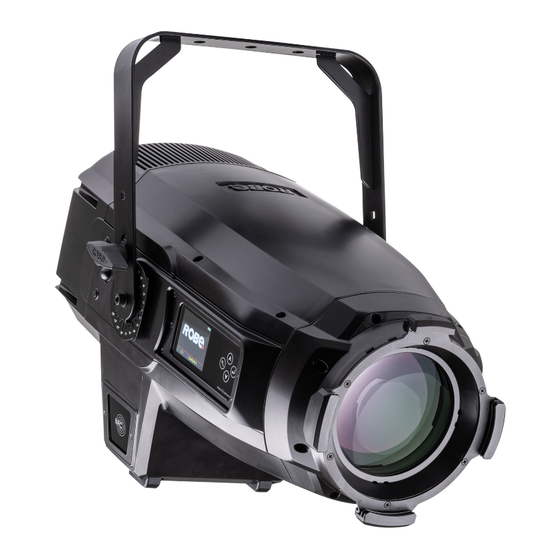
Page 6: Fixture Exterior View
2. Fixture exterior view 1 - Rear cover 2 - Tilt lock 3 - Control board 4 - Bottom cover 5 - Gel frame adaptor 6 - Front lens 7 - Top cover 8 - Yoke 9 - Battery cover 10 - Power Out (PowerCon True 1) 11 - Power In (PowerCon True 1) 12 - Fuse cover... -
Page 7: Installation
This device falls under class one and must be earthed (grounded). Ensure all connections and the power plug on the cable are properly sealed. Design of the ROBIN iT12 allows you to connect several fixtures to AC mains power in one interconnected daisy... -
Page 8: Replacing The Frost
chain using power input and throughput connectors. Needed daisy cables are stated in the chapter “Technical specifications “ Maximum number of linked fixtures depends on input voltage: 7 fixtures at power supply= 230V 5 fixtures at power supply= 230V 6 fixtures at power supply= 208V 5 fixtures at power supply= 208V 4 fixtures at power supply= 120V 3 fixtures at power supply= 120V... -
Page 9: Replacing Gobos
5. After replacing frost, check silica gel desiccants in the fixture head before placing top cover back on the fixture. 6. Place the top cover back on the fixture and screw it by means of the six hex socket head screws M5x16 before applying power. - Page 10 3. Disconnect two cables from DPS RB3698. Disconnect the two cables 4. Unscrew two screws (3) and take the drop-in gobo and animation wheel module (4) out of the chassis in order to get access to the rotating gobo wheel (5) and to the static gobo wheel (6).
- Page 11 - Remove the original gobo (8) and insert the new one (glossy side towards the light source). The Robe gobo has a small position point (11) at its edge which has to aim at the position point (10) on the gobo holder (9). Insert the spring lock (1) to secure correct position of gobo in the gobo holder.
- Page 12 5. After changing desired gobos, insert the drop-in gobo and animation wheel module (4) back to the chassis of the fixture and tighten two screws (3). 6. Connect two cables back to DPS RB 3698. 7. Check silica gel desiccants in the fixture before placing top cover back on the fixture. 8.
-
Page 13: Fresnel Lens/Pc Lens/Profile Lens Module Installation
3.4 Fresnel lens/PC lens/Profile lens module installation Install the front lens module with the device unplug from mains. Be careful, the front lens module is heavy! Do not replace front lens module in a damp environment (e.g. rain, snowfall)! Do not replace front lens module in smoky or particularly dirty environment (e.g. -
Page 14: Rigging The Fixture
3.5 Rigging the fixture A structure intended for installation of the fixture(s) must safely hold weight of the fixture(s) placed on it. The structure has to be certificated to the purpose. The fixture (fixtures) must be installed in accordance with national and local electrical and construction codes and regulations. - Page 15 Use only the safety wire with a snap hooks with screw lock gates. When installing fixtures side-by-side, avoid illuminating one fixture with another! DANGER TO LIFE! Before taking into operation for the first time,the installation has to be approved by an expert! Allowed installation positions of the iT12.
- Page 16 Note for open-air installation: if the fixture stands on the ground, min. distance of 4" (10cm) between the fixture base and the ground has to be kept.
-
Page 17: Dmx-512 Connection
3.6 DMX-512 connection The fixture is equipped with 5-pin XLR sockets for DMX input and output.The sockets are wired in parallel. Only use a shielded twisted-pair cable designed for RS-485 and 5-pin XLR-plugs and connectors in order to connect the controller with the fixture or one fixture with another. DMX output DMX input XLR mounting sockets (rear view):... -
Page 18: Ethernet Connection
The Universe is a single DMX 512 frame of 512 channels. The Robin iT12 is equipped with 8-pin RJ- 45 sockets for Ethernet in/out.Use a network cable category 5 (with four “twisted” wire pairs) and standard RJ-45 plugs in order to connect the fixture to the network. - Page 19 Ethernet / DMX operation Option “ Artnet" (gMaI or gMA2 or sACN) has to be selected from “Ethernet Mode” menu at first fixture. Option “Ethernet To DMX” has to be selected from the “Ethernet Mode” menu at the first fixture (connected to the Ethernet) in the fixture chain, next fixtures have standard DMX setting.
-
Page 20: Wireless Dmx Operation
The wireless DMX version of the fixture is equipped with the wireless DMX/RDM module which has full support for wireless communication protocols at entertainment market. The module is based on well known Lumen- Radio RF technology, with implemented wire interface for connection with Robe products. RF output for MCX interface antenna as standard output. -
Page 21: Checking The Ip65 Integrity Of The Fixture
4. Checking the IP65 integrity of the fixture. The Robin iT12 is IP65 rated lighting fixture which has been designed to be protected against the ingress of dust and pressure water jets from any direction. 1. Smart pressure test - for this test serves the function "Pressure Test" in the tab Service. Unique testing procedure allows you easy testing of the IP65 integrity of the fixture. - Page 22 "Enhanced pressure test". For this type of pressure test is needed the Pressure IP Testing Set ROBE (P/N 10980659). Please ask your ROBE distributor for help. The message "Valve Seal Error" means that valve or coil in the valve is defective or there is a connection problem.
-
Page 23: Operating The Fixture At Ambient Temperatures Below 0°C
150 mbar maximally! 5. Operating the fixture at ambient temperatures below 0°C Design of the iT12 allows its operation at ambient temperature up to -30°C, but you have to take some specific into account before operating the fixture. 1.Fixture is not in Standby mode. -
Page 24: Standby Mode
6. Standby mode The fixture can be switched to Standby mode by means of web interface REAP or DMX command (channel Power/Special functions, DMX values 6-7). Standby mode can be cancelled by means of web interface REAP, DMX command (channel Power/Special functions, DMX values 8-9) or by switching the fixture off and on. -
Page 25: Remotely Controllable Functions
7. Remotely controllable functions 7.1 Colour influencing functions Factory setting of menu functions (channels) which influence behaviour of colour channels is the following: Function Factory setting Function Factory setting DMX mode Uniformity Colour calibration mode Colour mix control 0 DMX Colour mixing mode 110 DMX (5600K) Dimmer curve... - Page 26 Colour Mix control (DMX channel "Colour Mix control") The Colour Mix control channel defines relation between colour channels (Cyan, Magenta, Yellow, Red, Green, Blue, Amber, Lime Green and CTO ) and the colours on the virtual colour wheel: DMX value Function 0 - 9 Virtual colour wheel has priority over colour channels (default setting)
- Page 27 Green correction (DMX channel "Green correction ") The channel allows you a fine correction of colours (whites, mixed colours, colours on the Virtual colour wheel). E.g. white colour from red to green tint. Virtual colour wheel (DMX channel " Virtual colour wheel") The virtual colour contains 67 preset colours and 10 user colours.
-
Page 28: Effect Functions
Motorized focus allows to focus beam from approx. 2 meters to infinity. The Robin iT12 also includes Brake Attribute Retention System (BARS), which allows remote locking and re- leasing individual motorised zoom and focus. It allows motors to be locked securely in place and only released on command. -
Page 29: Control Menu Map
8. Control menu map Default settings=Bold print Level 1 Level 2 Level 3 Level 4 Level 5 Level 6 Addressing Settings DMX Address 001-512 DMX Presets Mode 1 Mode 6 View Selected Preset Ethernet Settings Ethernet Mode Disable ArtNet gMAI gMA2 sACN Ethernet To DMX... - Page 30 Level 1 Level 2 Level 3 Level 4 Level 5 Level 6 Module L2 Module L3 Module O Module F-A Module F-B Module G Module DL Wireless Product IDs Mac Address RDM UID RDM Label LED Module info First Module Assembly Assembly History LED Modules History View Logs...
- Page 31 Level 1 Level 2 Level 3 Level 4 Level 5 Level 6 Recalibrate Touchscreen Display Orientation Normal Inverted Auto Temperature Unit °C,°F Auto Fan Settings Fan mode High Quiet Quiet mode-Blackout On, Off Fan Off Dimmer Curve Linear Square Law Super square Law Max.
- Page 32 Level 1 Level 2 Level 3 Level 4 Level 5 Level 6 Dimmer Fine 0-255 Calibrations Calibrate Effects Effect Wheel 0-255 Static Gobo Wheel 0-255 Rot. Gobo Wheel 0-255 R. Gobo Index 1 0-255 R. Gobo Index 7 0-255 Zoom 0-255 Focus 0-255...
-
Page 33: Control Menu
9. Control menu The Robin iT12 is equipped with the QVGA screen with battery backup and four control buttons which allow you to set the fixture´s behaviour according to your needs, obtain information on its operation, test its various parts and program it, if it has to be used in a stand-alone mode. - Page 34 Press the [ENTER/Display On] button to display the initial screen with the current stored DMX address: Note: The green icon at the top right corner of the screen indicates the level of the display battery charging. If the whole icon is green, the battery is fully charged while the red icon indicates exhausted battery. The battery charges during fixture operation, its charging lasts cca 6 hours.
- Page 35 REAP. Locking/unlocking the screen. To lock the screen, display the screen with ROBE logo, touch the [ESCAPE] button and slide your finger clockwise in a circular track of 360° across buttons [ESCAPE] --> [NEXT] --> [ENTER/Display On] -->[PREV]--> [ESCAPE].
-
Page 36: Tab " Address
Resetable Hours - The item shows the number of the operation hours that the Robin iT12 has been powered on since the counter was last reset. In order to reset this counter to 0, touch the text box next to the item "Resetable Hours:"... - Page 37 RAINS Status - The menu item gives you information about environment in the fixture. RAINS (Robe Automatic Ingress Neutralization System) manages humidity, temperature and pressure control using an active monitoring system to automatically remove any moisture detected within the fixture and provides permanent monitoring to ensure peak performance of the fixture.
- Page 38 Examples of RAINS statuses: Dry desiccants in the fixture Desiccants in the fixture partially saturated with water Desiccants in the fixture fully saturated with water Silica gel desiccants in the fixture are saturated with water and should be replaced. After replacing desiccants, reset the item MAX WET. Sensors Info - The menu items shows you current conditions in the fixture head (at pressure sensor): temper- ature, relative humidity and pressure.
-
Page 39: Tab "Personality
First Module Assembly - Use the item to read initial information about the LEDs module installed in the fixture. The fixture has to be connected to mains to read the values in the menu items. Serial Number/ Device UID - a serial number of the LEDs module/RDM UID of the fixture. Installation Date/Time - a date/time of the first installation of the LEDs module to a some Forte device. - Page 40 Distribute User Colour - The item allows you to "send" user colours from this fixture to all connected Robin iT12 fixtures by means of RDM protocol. User colours in the fixtures will be overwritten. Tungsten effect simulation - This function simulates behaviour of a halogen lamp during dimming at calibrated whites 2700K-4200K.
-
Page 41: Tab "Manual Control
-Use the menu to run a test/demo sequences without an external controller, which will show you some possibilities of using Robin iT12. Preset Playback - This menu allows you to select the program which will be played in a loop after switching... -
Page 42: Tab "Service
Play Program 1 - The option starts user program No.1. Play Program 2 - The option starts user program No. 2. Edit Program - Use the menu to create or to edit desired program. The Robin iT12 offers 2 free programs, each up to 68 steps. - Page 43 Iris - an iris fine movement (value range: 0-255) Frost 1/1 - a light frost fine position movement 1 Frost 1/2 - a light frost fine position movement 2 Frost 2/1 - a medium frost fine position movement 1 Frost 2/2 - a medium frost fine position movement 2 Fr.
- Page 44 If you use the Robe Universal Interface, connect a USB port of your computer with the Robe Universal Interface by means of the USB cable and DMX input of the fixture with the DMX output of the Robe Universal Interface via a DMX cable.
- Page 45 The Software Uploader program will start to run. 6. Select correct "COM " number if you use a Flash cable RS232/DMX or select "Robe Universal Interface " if you use the Robe Universal Interface/Robe Universal Interface WTX and then click on the "Connect" button.
-
Page 46: Rdm
DMX512, the RDM protocol allows a console or dedicated RDM controller to send commands to and receive messages from specific moving lights. RDM allows explicit commands to be sent to a device and responses to be received from it. The list of commands for Robin iT12 is the following. Parameter ID Discovery command SET command... -
Page 47: Error And Information Messages
11. Error and information messages Error in the fixture is signalled by the yellow warning icon at the bottom line of the screen. List of error and information messages: Prism 1 Error 1 Impact to the mechanical end of the prism wheel track was not detected. Prism 1 Error 4 Incorrect detection of a prism wheel track. - Page 48 Gobo Rotation Error 2 Magnetic/optic sensor permanently detects rotating gobo on the gobo carousel. Static Gobo Error 1 Magnetic/optic sensor was not detected. Static Gobo Error 2 Magnetic/optic sensor permanently detects static gobo wheel. Effect Wheel Error 1 Impact to the mechanical end of the effect wheel track was not detected. Effect Wheel Error 4 Incorrect detection of an effect wheel track.
- Page 49 Internal Error 2 Communication error (some PCB has failed or is disconnected (this PCB will show as N/A in menu --> Infor- mation --> Software versions) or error/noise was detected on communication wires). Blue 1 Short Error/ Blue 2 Short Error/ Blue 3 Short Error/ Blue 4 Short Error/ Blue 5 Short Error Some blue LEDs in the light source have short circuit or are disconnected.
-
Page 50: Nfc
The NFC point is situated on the side of the fixture. NFC point Download and install the ROBE COM from Google Play (for Android 5.0 and higher) or App Store (for iOS 12.0 and higher) to your mobile phone. Your mobile phone has to support NFC (Near-Field Communication). -
Page 51: Maintenance
Another maintenance and service operations should be carried out by trained technician only. If you need any spare parts, please order genuine parts from your local Robe distributor. Fixture metal covers are made of material resistant to corrosion, potential damages of covers (like scratches, abrasions) are only appearance defects and will not cause corrosion of covers. - Page 52 4. Place a new battery (only the same type) into the battery holder (Negative (-) inside, Plus (+) outside). 5. Place and tighten the battery holder cap (4) back. 6. Place the cover (2) with gasket (3) back on the rear panel of the fixture and fasten it by means of two screws (1) with sealing rings (3).
-
Page 53: Fixture Watertight Covers And Torques Of Covers Screws
13.1 Fixture watertight covers and torques of covers screws Keep values of torques as stated on pictures below otherwise leakage issues can occur! Run the procedure Pressure Test (Service Pressure Test) after replacing --> any watertight cover! Top cover Screws must be tightened 6 x hex socket head screw M5x16 in the order 1-->6 Tightening torque*: 2.5 Nm... - Page 54 Bottom cover Screws must be tightened 6 x hex socket head screw M5x16 in the order 1-->6 Tightening torque*: 2.5 Nm * Tighten all screws in two steps: Step 1 - use tightening torque 0.5Nm (pre-tightening) Step 2- use tightening torque 2.5Nm (final tightening) Carefully check the gasket for signs of deformities or damages and if it is correctly placed before screwing the top cover back.
- Page 55 Front lens module Screws must be tightened 8 x captive screw (Phillips head) in the order 1-->8 Tightening torque*: 2.5 Nm * Tighten all screws in two steps: Step 1 - use tightening torque 0.5Nm (pre-tightening) Step 2- use tightening torque 2.5Nm (final tightening) Carefully check the gasket for signs of deformities or damages and if it is correctly placed before screwing the front lens module on the fixture.
-
Page 56: Changing The Led Light Source
13.2 Changing the LED light source The Robin Forte allows you to change the LED light source and this way keep a high performance of the fixture. Unplug the fixture from mains before replacing LED light source! Do not change LED light source in a damp environment (e.g. rain, snowfall)! To change the LED light source. - Page 57 Fixture without the LED light source. Important: Carefully check the gasket (7) for signs of deformities and if it is correctly placed in the chassis of the fixture before inserting the new LED light source. The new LED light source includes PCB with LEDs and heat sink. Handle with care. Do not touch LEDs with bare hands.
- Page 58 4. Carefully insert the new LED light source to the head. Keep the correct orientation of the LED light source towards the head chassis as shown on the picture below. The NFC module on LEDs PCB has to be ori- ented towards the sign NFC on the fixture chassis.
- Page 59 5. Tighten the four outside fastening screws M4x14 (4) in the order 1-->4. Use tightening torque 2.5 Nm. Do the tightening of screws in two steps, in the first step use tightening torque 0.5 Nm and in the second step 2.5 Nm.
-
Page 60: Checking And Replacing The Silica Gel Desiccants
13.3 Checking and replacing the silica gel desiccants The silica gel desiccants are used for humidity indication in the fixture. Dry silica gel has an orange colour, if it is saturated with water, its colour changes to dark grey. If most of silica gel changed colour to dark grey, it has to be replaced. - Page 61 Example: Dry silica gel Silica gel saturated with water The silica gel desiccants in the fixture should be checked (and alternatively replaced) at removing head covers, e.g. at gobos change or some service intervention. After checking/replacing desiccants do not forget to connect grounding wire between chassis and top cover at placing the top cover back on the fixture.
-
Page 62: Disposing Of The Product
In case that silica gel in the fixture is fully saturated with water, the warning message " Too Much Humidity in Device" will appear on the fixture display (yellow warning icon) and also in the Robe Ethernet Access Portal (Logs screen). -
Page 63: Obtaining Information About The Led Light Source By Mobile Phone
14. Obtaining information about the LED light source by mobile phone You can read information about the LED light source by means of the mobile application ROBE COM. The LED light source has to be outside of the fixture. Download and install the application ROBE COM from Google Play (for Android 5.0 and higher) or App Store (for iOS 12.0 and higher) to your mobile phone. - Page 64 If NFC connection is OK, the screen with RDM UID of the LED light source will appear. When the following screen will appear, touch the button CANCEL. Touch the found LED module ("Robin iT12 LED module") and than touch "LED engine" to read information about found LED module.
-
Page 65: Robe Ethernet Access Portal (Reap)
You do not need change any IP settings on the fixture, there is no need to set the fixture into Art-Net mode. Type the IP address of the iT12 to your web browser, e.g. http://2.247.232.8, enter the user name: robe and the password: 2479, the Status screen of the iT12 will appear. - Page 66 10 minutes of its operating, after closing fixture dimmer etc. RAINS (Robe Automatic Ingress Neutralization System) manages humidity, temperature and pressure control using an active monitoring system to automatically remove any moisture detected within the fixture and provides permanent monitoring to ensure peak performance of the fixture.
- Page 67 Desiccants saturated with water Device status ready means, that all fixture resets are OK and the fixture is ready for operation. It does not assess state of desiccants or result of pressure test! Desiccants fully saturated with water Silica gel desiccants in the fixture should be replaced. After replacing them, reset MAX WET resettable bar chart.
- Page 68 The Personality screen allows you to set fixture behaviour and run a pressure test. The icon allows you to change values in a corresponding table. Example for Screen settings: The table "Pressure test " with green button Start test allows you to run a procedure which checks IP65 integrity of the fixture.
- Page 69 Examples of pressure test messages: Pressure test is 10 minutes delayed due to fixture cooling Pressure test is running Pressure test passed Pressure test failed The Logs screen displays operating information of the fixture which have been saved. The icon offers you two options: "Download log file"...
- Page 70 The option Logs filter allows you to select desired group of recorded errors and recorded operating values. Expanded menu Logs filter If the option "all must pass" is checked, only logs which contain all selected errors will be displayed. Menu "Sorting filter pass" --> option "single groups" means that logs which contain at least one selected error will be displayed.
- Page 71 Tab Pressure measurements shows history of pressure tests. If you have two and more iT12s, the Discovery screen allows you to show all connected iT12 fixtures in network. Click on the blue button Discover and fixtures connected in the network will be displayed.
- Page 72 If the option Move devices with warning to top is checked, fixtures with some error will be displayed on the top of fixture list. The option Columns selection allows you to check desired items which will be displayed in columns. Max. 6 items can be selected.
-
Page 73: Technical Specifications
16. Technical Specifications Electrical specification Power supply: electronic auto-ranging Input voltage range: 100-240V, 50-60Hz Fuse: T 6.3 A Max. power consumption: 440W (power factor: 0.97) Optical system Light source: MSL-TE™ 500W LED engine (Red, Green, Blue, Amber, Lime) CMY/RGB/RGBAL colour mixing CRI setting range: Standard (85) - High (90+) Typical lumen maintenance: L70/B50 @ 40.000 hours Light source warranty: 4 years or 20.000 hours... - Page 74 Frost filters separate,variable frost filters ( light (1°) and medium (5°)) The medium filter is replaceable Iris Motorized iris for different beam diameters Framing shutters module 4 individually positionable shutters plus rotation of the complete frame system +/- 60° Each framing shutter can be swiveled Zoom Linear motorized zoom Min.
- Page 75 Daisy Chain powerCON TRUE1 In/Out, EU, 2m, Outdoor (P/N 13052280) Daisy Chain powerCON TRUE1 In/Out, US, 2m, Outdoor (P/N 13052281) Doughty Trigger Clamp (P/N 17030386) Safety wire 35 kg (P/N 99011963) Drop-in gobo and animation wheel module iT12 (P/N 10980968) Drop-in framing and iris module iT12 (P/N 10980969)
- Page 76 Dimensions (mm)
-
Page 77: Changelog
Gobo change procedure changed 13/12/2023 Error messages changed January 5, 2024 Copyright © 2023 -2024 Robe Lighting - All rights reserved All Specifications subject to change without notice Made in CZECH REPUBLIC by ROBE LIGHTING s.r.o. Palackeho 416/20 CZ 75701 Valasske Mezirici... - Page 78 DMX protocol Robin iT12 - DMX protocol Version: 1.0 Mode 1=CMY/RGB, Mode =Reduced CMY/RGB, Mode 3=Five colours (R,G,B,A,Lime Green) Mode 4= Mode 1+ Gobo module, Mode 5=Mode 2+Gobo module, Mode 6=Mode 3+Gobo module Quick overview of default DMX values for each channel...
- Page 79 DMX protocol Mode/channel Default Function DMX Value Framing shutter 1- swivelling Framing shutter 2- movement Framing shutter 2- swivelling Framing shutter 3 movement Framing shutter 3- swivelling Framing shutter 4 movement Framing shutter 4- swivelling Shutter/ strobe Dimmer intensity Dimmer intensity - fine Mode/channel Type of Function...
- Page 80 DMX protocol Mode/channel Type of Function Value control 132-133 Optics Brake Off step 134-137 Reserved 138-139 Cue Playback - saving current DMX values step 140-141 Preset Cue playback On - fixture playes the Cue automaticaly after every switching On step 142-143 Preset Cue playback Off - fixture listens to DMX, but only this step channel and DMX values 142-143...
- Page 81 DMX protocol Mode/channel Type of Function Value control Selected LED Frequency (128=default) step LED Frequency (step +1) step LED Frequency (step +2) step LED Frequency (step +3) step LED Frequency (step +124) step LED Frequency (step +125) step LED Frequency (step +126) step Selected LED Frequency step...
- Page 82 DMX protocol Mode/channel Type of Function Value control Filter 79 (Just Blue) 15-16 step 17-18 Filter 88 (Lime Green) step 19-20 Filter 90 (Dark Yellow Green) step 21-22 Filter 100 (Spring Yellow) step Filter 101 (Yellow) 23-24 step Filter 102 (Light Amber) 25-26 step Filter 103 (Straw)
- Page 83 DMX protocol Mode/channel Type of Function Value control 111-112 Filter 205 (Half C.T. Orange) step 113-114 Filter 206 (Quarter C.T. Orange) step 115-116 Filter 247 (Filter Minus Green) step 117-118 Filter 248 (Half Minus Green) step 119-120 Filter 281 (Three Quarter C.T. Blue) step 121-122 Filter 285 (Three Quarter C.T.
- Page 84 DMX protocol Mode/channel Type of Function Value control 0 - 255 Colour saturation control - fine (255=default) proportional Blue (8 bit) 0 - 255 Colour saturation control - coarse 0-100% (255=default) proportional Blue (16bit) 0 - 255 Colour saturation control - fine (255=default) proportional Amber (8 bit) 0 - 255...
- Page 85 DMX protocol Mode/channel Type of Function Value control Function is off (0=default) step 1-255 Time of stat. Gobo and rot. Gobo carousel movement (0.1 sec-->25.5 sec.) proportional Time of framing shutters, zoom, focus and frost movement (0.1 1 - 255 sec-->25.5 sec.) proportional Effect wheel positioning...
- Page 86 DMX protocol Mode/channel Type of Function Value control 128-139 Gobo 4 proportional 140-151 Gobo 5 proportional 152-163 Gobo 6 proportional 164-175 Gobo 7 proportional 176-187 Gobo 8 proportional 188-199 Gobo 9 proportional 200 - 201 Open/hole step 202 - 222 Forwards gobo wheel rotation from fast to slow proportional 223 - 243 Backwards gobo wheel rotation from slow to fast proportional...
- Page 87 DMX protocol Mode/channel Type of Function Value control Gobo 6 proportional Gobo 7 proportional Open/hole proportional 190-201 Open/hole step 202 - 222 Forwards gobo wheel rotation from fast to slow proportional 223 - 243 Backwards gobo wheel rotation from slow to fast proportional 244 - 249 Reserved 250 - 255 Auto random gobo selection from fast to slow...
- Page 88 DMX protocol Mode/channel Type of Function Value control Pulse effects with Iris blackout 192 -219 Pulse opening from slow to fast proportional 220 - 247 Pulse closing from fast to slow proportional 248 - 249 Random pulse opening (fast) step 250 - 251 Random pulse opening (slow) step 252 - 253 Random pulse closing (fast)
- Page 89 0 - 255 Dimmer intensity from 0% to 100% (0=default) proportional Dimmer intensity - fine 0 - 255 Fine dimming (0=default) proportional Copyright © 2023 Robe Lighting s.r.o. - All rights reserved All Specifications subject to change without notice Page 12...
Need help?
Do you have a question about the iT12 and is the answer not in the manual?
Questions and answers