Table of Contents
Advertisement
Quick Links
Advertisement
Table of Contents

Related Manuals for Dometic ASCDU15HV 1161


Summary of Contents for Dometic ASCDU15HV 1161
- Page 1 Service Manual . . . . . . . . . . . . . . . . . . . . . 2 L-5502 | Form No. 340949 20200317 | ©2020 Dometic Corporation...
-
Page 2: Table Of Contents
Supplemental Directives ....3 Servicing the Dometic Q Heat Relay ..35 General Safety Messages ....3 Servicing the Compressor Assembly . -
Page 3: Explanation Of Symbols And Safety
CAUTION Indicates a hazardous situation that, if not avoided, • Use only Dometic replacement parts and could result in minor or moderate injury. components that are specifically approved for use with the appliance. -
Page 4: Intended Use
Intended Use Air Conditioner 2 Intended Use Review the "Troubleshooting Table" on page 4 to help identify the suspected operational issue, This service manual is intended for use by OEM installers the potential causes, and the diagnostic procedure and dealer technicians. Manual users are assumed to associated with those issues. - Page 5 Air Conditioner Troubleshooting Operational Issue Potential Reason Page The system has low supply-air flow. The evaporator fan coil is iced. The evaporator fan coil is dirty. The evaporator air filter is dirty. The evaporator fan speed is set on low or manual low. The evaporator blower capacitor is defective.
- Page 6 There is an obstruction or object in the blower wheel. There is a bad Q3 control. There is no heat. The Dometic Q heat relay is defective. The auxiliary heater thermal overload switch is faulty. The auxiliary heater element has an open circuit.
- Page 7 Air Conditioner Troubleshooting Operational Issue Potential Reason Page There is no cooling. The temperature set point is satisfied. The Q3 control is in Manual Fan mode. The Q3 control is in Heat mode. The condenser airflow is obstructed. The evaporator airflow is obstructed. The system has lost refrigerant.
-
Page 8: General Information
Compressor Contactor (30 A, 115 V) Compressor Run Capacitor 4 .1 Tools and Materials Compressor Start Capacitor Dometic recommends that the following tools and Compressor Start Relay materials be used while servicing the refrigerator: Compressor Thermal Overload Switch Recommended Tools... -
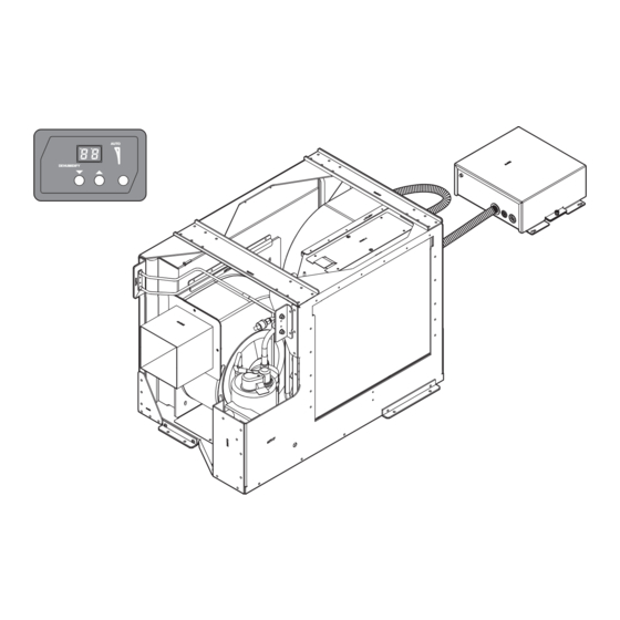
Page 9: System Component Identification
4 .3 System Component Identification Figure 2 shows the locations of the major components within the ASCDU15HV 1161 Air Conditioning Unit. 2 ASCDU15HV 1161 Air Conditioning Unit Component Locations Q3 Control Unity Control Board Evaporator Blower Assembly Compressor Contactor (30 A, 115 V) -
Page 10: Q3 Control Overview
Specifics regarding the Q3 control operation have been included in "Service Procedures" on page 32 Figure 3 identifies the buttons on the Q3 control used and "Programmable Functions, Ranges, and Factory with the ASCDU15HV 1161 Air Conditioning Unit. Defaults" on page 13. AUTO COOL... -
Page 11: General Air Conditioning Terminology
Air Conditioner Troubleshooting 4 .5 General Air Conditioning • R-410A refrigerant cylinders are light maroon (pink). Terminology • R-410A refrigerant cylinders have a dip tube that allows liquid to flow out of the cylinder in an upright The following table defines some of the terms that are position. -
Page 12: Q3 Control And Ascdu15Hv 1161 Wiring
Troubleshooting Air Conditioner 4 .7 Q3 Control and ASCDU15HV 1161 Wiring Diagram This diagram shows the wiring specifications for the unit. *NOTES: 1. JUMPER #2 (JP2) MUST BE REMOVED WHEN USING LOW PRESSURE SWITCH OPTION. 2. IF PRESENT ON BOARD, JUMPER (CSNB) MUST BE CUT WHEN USING A CONTACTOR OR SOLID STATE RELAY ON THE COMPRESSOR OUTPUT. -
Page 13: Programmable Functions, Ranges, And Factory Defaults
Quick Reference Table Ranges, and Factory Defaults This table shows the specifications and explanations of the various functions available for the ASCDU15HV 1161 This section provides information on the programmable Air Conditioning Unit. functions, ranges, and factory defaults of the ASCDU15HV 1161 Air Conditioning Unit. - Page 14 Troubleshooting Air Conditioner Function Number Description Factory Default Required Settings Function Range Anti-Icing Routine 65–80 °F 70 °F (21 °C) – Adjustment (18–26 °C) 3 = 3 speeds Fan-Speed Divisions – 5 = 5 speeds - - = Aux Heat/Heat The Q3 control MUST Disabled Aux Heat/Heat be set to “h1”...
- Page 15 3 °F average room temperature. Check with your dealer (-16 °C) above the set point. or call Dometic for more information. 5: Low Fan Speed 8: AC Line Voltage Calibration You can adjust the lowest fan speed to suit individual The unity control board assembly has a built-in voltmeter preferences.
- Page 16 Troubleshooting Air Conditioner 9: Temperature Calibration The factory settings are adequate for most moderate climates and boats. For very humid climates, shorten This feature calibrates the ambient sensor within a range the overall time period and extend the dehumidification of ±1%. The temperature sensor should be within one or time.
- Page 17 Air Conditioner Troubleshooting 14: Determining Your Product Type The high-pressure switch test is used to test the high- pressure circuit for a fault, an overcharged system, or The system default is dE for “direct expansion self- the loss of air flow. Press the Mode button to enter the contained.”...
- Page 18 100 hours. Function values are between 1 (ten minutes minus 45 seconds), repeating in ten- (100 hours) and 25 (2500 hours). Dometic recommends minute intervals. You may adjust the conditioned space that you check the air filter at least every 500 hours of temperature at which the anti-icing routine is initiated.
-
Page 19: Programming The Q3 Control
Air Conditioner Troubleshooting If function 22 is set to five and function 30 is set to five, 2. Press the Up or Down buttons to scroll until the you can modify three more fan speeds (medium low, desired programmable function number (1–29) is displayed. -
Page 20: Diagnostic Procedures
Q3 control (refer to "Error- installation, or operational issues. Refer to "Power/ Based Diagnostics" on page 26). Installation Issues" on page 28, "Operation Checks" on page 29, or "Q3 Control and ASCDU15HV 1161 Wiring Diagram" on page 12 for more details. Component Diagnostic Question... -
Page 21: Auxiliary Heater
Is the heater not operating? Check the auxiliary heater thermal overload switch for continuity. Check the electrical connections to the Dometic Q heat relay. Verify the resistance in the auxiliary heater circuit. The auxiliary heater resistance should read approximately 5.3 Ohms. -
Page 22: Compressor Contactor (30 A, 115 V)
Diagnostic Procedures Air Conditioner Component Diagnostic Question Action Based On Status Page Compressor Assembly (continued) Does the compressor Test the high-pressure switch. stop on the high- 23, 44 pressure switch when the Check that the airflow through the condenser coil condenser fan is on? is not restricted. -
Page 23: Compressor Run Capacitor
Air Conditioner Diagnostic Procedures Component Diagnostic Question Action Based On Status Page Compressor Run Capacitor Is the compressor not Check the mF value of the compressor run capacitor running? for 60 mF. If the mF value of the capacitor is incorrect, replace the compressor run capacitor. -
Page 24: Condenser Blower Capacitor
Is there no heat? Use a multimeter to test for power in L1 and out T2 of the Dometic Q heat relay when the Q3 control is calling for heat. If there is no power at T2, test using the following steps: Remove the T2, L1, YEL, and L2 wires from the Dometic Q heat relay board. -
Page 25: Evaporator Blower Capacitor
Air Conditioner Diagnostic Procedures Component Diagnostic Question Action Based On Status Page Evaporator Blower Capacitor Is the evaporator fan slow Test the mF value of the evaporator blower capacitor or not running? for 20 mF. If the mF value is incorrect, replace the evaporator blower capacitor. -
Page 26: Error-Based Diagnostics
Diagnostic Procedures Air Conditioner Component Diagnostic Question Action Based On Status Page Unity Control Board Is there a red LED Use a multimeter to check the voltage between L1 and illuminated on the unity L2. Proper voltage should be 115 VAC. control board? If there is power and no light illuminated, replace the unity control board. - Page 27 Air Conditioner Diagnostic Procedures Code Description Possible Cause Possible Action Page LO/PS The suction pressure is below the A loss of refrigerant occurred in Check for leaks in the minimum preset limit. system. system. The ambient temperature is too low Verify the ambient for cooling.
-
Page 28: Faults And Error Messages
Power/Installation Issues Air Conditioner 5 .3 Faults and Error Messages If after eight attempted compressor starts, the low- pressure switch does not stay closed, the unit will go To protect the equipment, certain fault conditions into a sustained shutdown and the Q3 control alternates trigger a shutdown, and the system will not restart until flashing “LO”... -
Page 29: Installation Issues
• Refer to the "Q3 air conditioning problem, always check the functionality Control and of the appliance before replacing components. This ASCDU15HV 1161 Wiring Diagram" on section contains information on how to properly operate page 12. the air conditioner and the Q3 control. -
Page 30: Understanding Button Functions
This unit is factory charged with the required amount of refrigerant. If refrigerant recharging is Cycle required, call Dometic for the proper amount of refrigerant required for this system. If you select Cool Mode, only cooling is supplied. If you select Heat, only heat is supplied. The conditioned... - Page 31 Air Conditioner Operation Checks 7 .3 .2 Dehumidification Mode 7 .3 .5 Nonvolatile Memory Press the Mode button until the Dehumidify LED The Q3 control has non-volatile memory requiring no indicator illuminates. The display flashes “HU” during batteries or backup power. When power is lost, the this mode of operation.
-
Page 32: Service Procedures
Air Conditioner 7 .3 .10 Anti-Ice Routine For any wiring actions in this section, refer to "Q3 Control and ASCDU15HV 1161 Wiring Diagram" on The Q3 control occasionally shuts down the compressor page 12. when in Cool Mode to allow any ice to melt that may have formed on the evaporator coil. -
Page 33: Charging The Unit
Air Conditioner Service Procedures 8 .3 Charging the Unit 2. To release lockout mode, press the Mode, Up, and Fan buttons simultaneously. “UL” displays Always charge the system with R-410A refrigerant momentarily and the buttons are unlocked for as a liquid. It is recommended to use a Charge normal operation. -
Page 34: Servicing The Auxiliary Heater
Service Procedures Air Conditioner 8 .6 Servicing the Auxiliary Heater 8 .7 Servicing the Auxiliary Heater Thermal Overload Switch Use this procedure to remove and install the auxiliary heater. Use this procedure to remove and install the auxiliary heater thermal overload switch. 7 Auxiliary Heater Thermal Overload Switch Removal Auxiliary Heater Thermal Overload Switch 1. -
Page 35: Servicing The Dometic Q Heat Relay
8 .8 Servicing the Dometic Q Heat 8 .9 Servicing the Compressor Relay Assembly Use this procedure to remove and install the Dometic Q Use this procedure to remove and install the compressor heat relay. assembly. 8 Dometic Q Heat Relay... -
Page 36: Servicing The Compressor Overload
1. Perform the steps in "Removing the Electrical Box Cover" on page 33. 2. Label all contactor connections prior to removal. Refer to "Q3 Control and ASCDU15HV 1161 Wiring 10 Compressor Overload Switch Removal Diagram" on page 12. Compressor Assembly Overload Switch 3. -
Page 37: Servicing The Compressor Run Capacitor
Air Conditioner Service Procedures 6. To reinstall, perform steps 1–5 in reverse. 7. Restore power to the system and ensure proper operation of the system. 8 .12 Servicing the Compressor Run Capacitor Use this procedure to remove and install the compressor run capacitor. -
Page 38: Capacitor
Service Procedures Air Conditioner 8 .13 Servicing the Compressor Start 8 .14 Servicing the Compressor Start Capacitor Relay Use this procedure to remove and install the compressor Use this procedure to remove and install the compressor start capacitor. start relay. 15 Compressor Start Relay Removal 14 Compressor Start Capacitor Removal Electrical Box... -
Page 39: Servicing The Condenser Blower
3. Label the four butt connector locations prior to removal for use during installation. Refer to "Q3 Control and ASCDU15HV 1161 Wiring Diagram" on page 12. 4. Disconnect the green wire to green wire butt splice and dispose of the butt splice. -
Page 40: Servicing The Evaporator Blower
3. Label the four butt connector locations prior to Cover" on page 33. removal for use during installation. Refer to "Q3 Control and ASCDU15HV 1161 Wiring Diagram" on 2. Disconnect the white/black wire and the brown/ page 12. white wire from the connectors on the bottom of the condenser blower capacitor. -
Page 41: Servicing The High-Pressure Switch
Air Conditioner Service Procedures 1. Perform the steps in "Removing the Electrical Box 5. To reinstall, perform steps 1–4 in reverse. Cover" on page 33. 6. Check for leaks. 2. Disconnect the brown wire from the evaporator 7. Restore power to the system and verify proper blower capacitor. -
Page 42: Servicing The Unity Control Board
3. Disconnect all of the wires secured within unity control board. Refer to "Q3 Control and the electrical box. Refer to "Q3 Control and ASCDU15HV 1161 Wiring Diagram" on page 12. ASCDU15HV 1161 Wiring Diagram" on page 12. 3. Remove the four screws securing the unity control 4. -
Page 43: Servicing The Q3 Control
Air Conditioner Service Procedures 8 .23 Servicing the Q3 Control 8 .23 .2 Replacing the Q3 Back Mounting Plate Use this procedure to remove and install the components of the Q3 control. 8 .23 .1 Replacing the Q3 Control Assembly 25 Back Mounting Plate Removal Q3 Back Mounting Plate Mounting Screws... -
Page 44: Maintenance
Maintenance Air Conditioner 1. Turn the electrical power to the unit off. Monthly 2. Disconnect the interconnect cable plug attached to Task Page the electrical box from the plug attached to the unit. Clean or replace the return-air filter. Check the condensate drain for blockages. Check for any obstructions in the system. -
Page 45: Checking The Condensate Drains
Consult a local recycling center or specialist dealer for details about how to dispose of the product in accordance with all applicable national and local regulations. 11 Replacement Parts For the most current parts information, visit www.dometic.com. - Page 46 Air Conditioner...
- Page 47 Air Conditioner...
- Page 48 Mobile living made easy. dometic .com YOUR LOCAL YOUR LOCAL YOUR LOCAL DEALER SUPPORT SALES OFFICE dometic .com/dealer dometic .com/contact dometic .com/sales-offices...
Need help?
Do you have a question about the ASCDU15HV 1161 and is the answer not in the manual?
Questions and answers