
Related Manuals for RKI Instruments 65-2405-04SS


Summary of Contents for RKI Instruments 65-2405-04SS
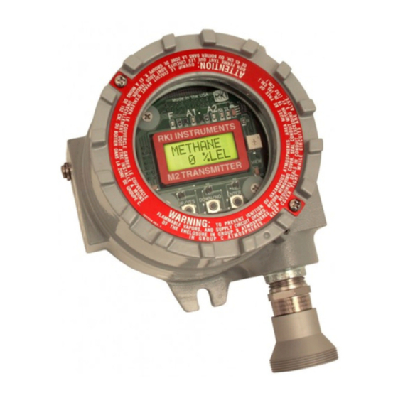
- Page 1 65-2405-04SS Combustible Gas Transmitter Operator’s Manual Part Number: 71-0659 Revision: P1 Released: 1/29/24 RKI Instruments, Inc. www.rkiinstruments.com...
- Page 2 For most applications, typical calibration frequencies are between 3 and 6 months but can be more often or less often based on your usage. 2 • 65-2405-04SS Combustible Gas Transmitter Operator’s Manual...
- Page 3 We do not assume indemnification for any accident or damage caused by the operation of this gas monitor and our warranty is limited to the replacement of parts or our complete goods. Warranty covers parts and labor performed at RKI Instruments, Inc. only, and does not cover field labor or shipment of parts back to RKI.
-
Page 4: Table Of Contents
Parts List ............23 4 • 65-2405-04SS Combustible Gas Transmitter Operator’s Manual... -
Page 5: Overview
Accuracy greater) WARNING: When using the 65-2405-04SS, you must follow the instructions and warnings in this manual to assure proper and safe operation of the 65-2405-04SS and to minimize the risk of personal injury. Be sure to maintain and periodically calibrate the 65-2405-04SS as described in this manual. -
Page 6: Description
Jumper Pins, Factory Use Only + Test Point - Test Point Detector Terminal Strip Detector Junction Box Combustible Gas Detector Calibration Adapter/ Splash Guard Figure 1: Combustible Gas Transmitter Component Location 6 • Description 65-2405-04SS Combustible Gas Transmitter Operator’s Manual... -
Page 7: Combustible Gas Detector
This drive current is factory set and is dictated by the combustible gas to which the detector is calibrated. Consult RKI Instruments, Inc. if you plan to change the calibration gas for the transmitter, for example from a methane calibration to a hexane calibration. The amplifier includes the detector terminal strip, controller terminal strip, span pot, zero pot, and test points (see Figure 1). -
Page 8: Amplifier Junction Box
A locking set screw on the junction box cover allows you to secure the junction box cover and prevent it from being removed. 8 • Description 65-2405-04SS Combustible Gas Transmitter Operator’s Manual... -
Page 9: Installation
Splash Guard Figure 2: Mounting the Combustible Gas Transmitter 2. At the monitoring site you select, hang or mount the detector junction box with the detector facing down (see Figure 2). 65-2405-04SS Combustible Gas Transmitter Operator’s Manual Installation • 9... -
Page 10: Wiring The Detector To The Amplifier
To make wiring more convenient, use wire colors that correspond to the detector wire colors: red, white, green, and black. NOTE: Consult RKI Instruments, Inc. for cable lengths longer than 200 feet. 5. Connect the detector leads to the terminal block in the detector junction box. - Page 11 Install a lug on the shield drain wire or wrap the shield drain wire around the mounting screw. Do not connect the shield drain wire at the detector junction box. 65-2405-04SS Combustible Gas Transmitter Operator’s Manual Installation • 11...
-
Page 12: Wiring The Amplifier To A Controller
The power cable may disrupt the transmission of the transmitter signal to the controller. 9. Connect the wires to the applicable detector/transmitter terminal strip at the controller as shown in Figure 4. 12 • Installation 65-2405-04SS Combustible Gas Transmitter Operator’s Manual... -
Page 13: Startup
2. Verify that the power wiring to the controller is correct and secure. Refer to the controller operator’s manual. 3. Turn on power to the controller. 4. Turn on the controller. 65-2405-04SS Combustible Gas Transmitter Operator’s Manual Start Up • 13... -
Page 14: Setting The Zero Signal
The procedure below describes applying zero emission air, usually called zero air, using a calibration kit that includes a calibration cup, calibration gas, sample tubing, and a fixed flow regulator with an on/off knob. RKI Instruments, Inc. recommends using a 0.5 LPM (liters per minute) fixed flow regulator. -
Page 15: Maintenance
Verify a display reading of 0 %LEL at the controller. Investigate significant changes in the display reading. Quarterly Calibrate the combustible gas transmitter as described in “Calibration” on page 20 of this manual. 65-2405-04SS Combustible Gas Transmitter Operator’s Manual Maintenance • 15... -
Page 16: Troubleshooting
3 months. become kinked, difficulties continue, replace the blocked, or detector. Some applications disconnected. 6. If the calibration/response may require a more difficulties continue, contact RKI frequent calibration for further instruction. schedule. 16 • Maintenance 65-2405-04SS Combustible Gas Transmitter Operator’s Manual... -
Page 17: Replacing Components Of The Combustible Gas Transmitter
CAUTION: Allow the replacement detector to warm up for 5 minutes before you continue with the next step. 13. Calibrate the transmitter as described in “Calibration” on page 20 of this manual. 65-2405-04SS Combustible Gas Transmitter Operator’s Manual Maintenance • 17... - Page 18 PWR/SIG “S” S (4 - 20 mA In) PWR/SIG “+” + 24V Table 4: Reconnecting the LEL Detector to the Amplifier Amplifier Detector Terminal Detector Lead Strip DETECTOR “R” DETECTOR “W” 18 • Maintenance 65-2405-04SS Combustible Gas Transmitter Operator’s Manual...
-
Page 19: Calibration Frequency
Although there is no particular calibration frequency that is correct for all applications, a calibration frequency of every 3 to 6 months is adequate for most combustible gas transmitter applications. Unless experience in a particular application dictates otherwise, RKI Instruments, Inc. recommends a calibration frequency of every 3 months. -
Page 20: Determining Response Time
0.5 LPM fixed flow regulator with an on/off knob, a calibration cup for the detector, and a short piece of sample tubing to connect the regulator to the calibration cup. 20 • Determining Response Time 65-2405-04SS Combustible Gas Transmitter Operator’s Manual... -
Page 21: Preparing For Calibration
1. Screw the regulator into the calibration cylinder. Verify that the calibration gas is representative of the transmitter’s target gas. 2. Turn the regulator’s on/off knob counterclockwise to open the regulator. 65-2405-04SS Combustible Gas Transmitter Operator’s Manual Calibration • 21... -
Page 22: Returning To Normal Operation
4. When the controller display reading falls below the alarm setpoints, return the controller to normal operation. 5. Verify that the controller display reading decreases and stabilizes at 0 %LEL. 6. Store the components of the calibration kit in a safe and convenient place. 22 • Calibration 65-2405-04SS Combustible Gas Transmitter Operator’s Manual... -
Page 23: Parts List
61-0140RK Combustible gas sensor 65-2405-04SS Methane transmitter (includes detector, two junction boxes, and amplifier) 71-0659 65-2405-04SS Combustible Gas Transmitter Operator’s Manual (this docu- ment) 81-0004RK-01 Steel calibration cylinder, 50% LEL propane in air, 34-liter 81-0012RK-01 Steel calibration cylinder, 50% LEL methane in air, 34-liter...
Need help?
Do you have a question about the 65-2405-04SS and is the answer not in the manual?
Questions and answers