
Related Manuals for TESTO 6631


Summary of Contents for TESTO 6631
- Page 1 6631 Bio research transmitter P2A-Software for testo 6631 Instruction manual...
-
Page 3: Table Of Contents
Contents 3 Contents Contents ..................... 3 Safety and the environment................. 4 Part 1: testo 6631 Specifications....................5 Product description ..................8 Commissioning ................... 9 Connecting instrument ..................9 Electrical connection ..................10 Parameterizing/adjusting/analyzing the instrument ......... 11 Maintaining the product ................12 Tips and assistance .................. -
Page 4: Safety And The Environment
Follow the prescribed steps when doing so. Use only OEM spare parts from Testo. Protecting the environment Send the product back to Testo at the end of its useful life. We will ensure that it is disposed of in an environmentally friendly manner. -
Page 5: Part 1: Testo 6631
Specifications Functions and use The testo 6631 is a bio research humidity transmitter for relative humidity and temperature. The sensors are located in the housing. The transmitter is available with an integrated display for the reading as an option (cannot be retrofitted by the customer). - Page 6 Language versions of the instruction manual Japanese-English Language versions of the instruction manual Chinese-English Sample orders testo 6631 ·· 4...20 mA (2-wire), with display, %rF/°C, Bedienungsanleitung Deutsch-Englisch: 0555 6631 / B01 / C01 / F01 / G02 / M05 / K01 Technical data Sensor Housing ·...
- Page 7 6631 - Specifications 7 Dimensions...
-
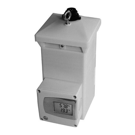
Page 8: Product Description
6631 - Product description Product description At a glance: Suspension ring Voltage supply / signal output Ventilator Ventilator drawer assembly (rear) Service opening for humidity sensor (rear) Mini-DIN-connection for P2A software and 1-point adjustment Two line display V entilation shaft... -
Page 9: Commissioning
6631 - Commissioning 9 Commissioning Connecting instrument Replacing ventilator: ã 1. Connect plug-in cable. 2. Place ventilator drawer assembly into housing. 3. Tighten screw on ventilator drawer assembly. Install instrument in a suitable position: ã Connect the supply line to the socket plug on the instrument. -
Page 10: Electrical Connection
6631 - Commissioning Electrical connection 2-wire technology · Plug manufacturer: Euchner · Cable socket (not included in delivery): Type BS 7K · Pin socket (fitted in instrument ex-works): Type SD 7K 1 %RH (4...20mA) 2 °C/°F (4...20mA) 3 AC ventilator... -
Page 11: Parameterizing/Adjusting/Analyzing The Instrument
Scaling beyond the measurement range allows the adaptation of the scaling limits to prescribed values from a PLC. The measurement range itself cannot be extended this way. The instrument is parameterized, adjusted and analyzed using the P2A Software, see “Part 2: testo P2A Software”. -
Page 12: Maintaining The Product
6631 - Maintaining the product Maintaining the product Caution! Never put your hands inside housing openings when the ventilator is running. This could lead to injury. Disconnect the instrument from the mains supply before cleaning or exchanging the ventilator, and wait until the ventilator has come to a standstill. - Page 13 6631 - Maintaining the product 13 Exchanging sensor â 1. Loosen screw on the ventilator drawer assembly. 2. Remove drawer assembly with the ventilator from the housing. 3. Disconnect plug-in cable. 4. Remove ventilator from drawer assembly using Allen key.
-
Page 14: Tips And Assistance
Designation Article no. Parameterizing, adjusting and analyzing software (P2A Software incl. adapter cable for USB to mini-DIN) 0554 6020 Process display testo 54-2 AC, two relay outputs (to 250 VAC/300 VAC, 3 A), mains power supply 90...260 VAC 5400 7553 Process display testo 54-7 AC, two relay outputs (to 250 VAC/300 VAC, 3 A), mains power supply 90...260 VAC, with RS485-output for Online Monitoring and with toatlizer display 5400 7555... -
Page 15: Part 2: Testo P2A Softwareÿ
The P2A software is used for the parameterization, adjustment and analysis of Testo transmitters. The following applies: • If a Testo transmitter is bought at a later stage (and is therefore more recent than the existing P2A software version), a software update is required. -
Page 16: First Steps
3. Click on [Finish] to complete the software installation. P2A Software update: â P2A software update 1. You can find the P2A software upgrade on the Testo website www.testo. com under the product-specific downloads. Download and save P2A software upgrade. 2. Start P2A upgrade.exe file. -
Page 17: Starting The Software
> Click on [Start] | right mouse button | Search | Enter the name of the application in the search field | P2A Software. (double-click on left mouse button). Windows® 10 > Click on [Start] | All Apps | Testo | P2A Software. (double-click on left mouse button). -
Page 18: Product Description
P2A Software - Product description Product description User interface 1 Menu bar. 2 Toolbar. 3 File list: List of all instrument/parameter files. File symbols · : Instrument file, connection to the unit has not been established. · : Instrument file, connection to instrument is established.„[Type] [Serial number].cfm“, File names cannot be altered. - Page 19 P2A Software - Product description 19 5 Instrument information: Information displayed · Instrument files: Type, serial number, firmware version and connection status of the instrument. · Parameter file: Type, serial number and firmware version of instrument with which the parameter file was created.
-
Page 20: Using The Product
P2A Software - Using the product Using the product Establishing a connection with the device: â Several instruments can be connected to the PC and administered via the P2A software, but only one connection can ever be active at any one time. - Page 21 As standard, the original name (instrument type, serial number) with the current date / time is suggested, e. g.. „testo 6631 01234578 061120 1403.cfp“. In a standard installation, the files are stored in the path „C:\ Documents and Settings\All Users\Common Documents\P2A Software“.
- Page 22 Carrying out a 2-point adjustment: â Before the 2-point adjustment, it must be ensured that the ventilator of the testo 6631 is operating, and that the air input opening is not blocked. Click on Adjust transmitter button. Select the adjustment point under 2-point adjustment.
- Page 23 P2A Software - Using the product 23 For the testo 6631, a 2-point adjustment can also be performed using the testo control and adjustment set (0554 0660). Please also refer to the instruction manual for the control and adjustment set. The reference...
- Page 24 P2A Software - Using the product Deleting parameters from an instrument/parameter file: â The parameter data for the selected instrument/parameter file can be deleted. The required instrument/parameter file is selected. Right-click on the instrument/parameter file. Select Delete. Click on Yes to confirm.
-
Page 25: Tips And Assistance
· Carry out factory reset: Click on > Carry out factory reset Click on If we could not answer your question, please contact your dealer or Testo Customer Service. For contact data, see back of this document or web page www.testo.com/service-contact... - Page 26 Testo SE & Co. KGaA Celsiusstr. 2 79822 Titisee-Neustadt Germany Tel.: +49 7653 681-0 E-Mail: info@testo.de www.testo.com 0970 6631 en 03...
Need help?
Do you have a question about the 6631 and is the answer not in the manual?
Questions and answers