Table of Contents
Advertisement
Quick Links
Advertisement
Table of Contents

Subscribe to Our Youtube Channel
Related Manuals for Hama 00 220849


Summary of Contents for Hama 00 220849
- Page 1 220849 TV WALL BRACKET G Operating Instructions...
-
Page 2: Table Of Contents
Contents 1. Explanation of warning symbols and notes ......3 2. Package contents ..........4 3. -
Page 3: Explanation Of Warning Symbols And Notes
G Operating Instructions Thank you for choosing a Hama product. Take your time and read the following instructions and information completely. Please keep these instructions in a safe place for future reference. If you sell the device, pass on the illustrated quick start guide and the safety instructions in printed form to the new owner. -
Page 4: Package Contents
2. Package contents • TV wall bracket • Drilling template • Mounting kit • Safety instructions, illustrated quick start guide Mounting kit 8x60 (x4) M8x20 (x4) Ø10x60 (x4) M8x30 (x4) M8 (x4) M8x50 (x4) M4x12 (x4) M6 (x4) Ø8x10 (x4) M4x20 (x4) Ø8x20 (x4) (x1) -
Page 5: Safety Instructions
4. Safety instructions Warning • Given the multitude of terminal devices and wall structures available on the market, the supplied mounting kit is unable to cover every option. • It occasionally happens that the screws for attaching the device to the bracket are too long. •... -
Page 6: Preparation And Assembly
6. Preparation and assembly Note • Never install the bracket alone. Seek assistance and help! • Different end devices have different connections for cabling and other devices. Before commencing the installation, check whether the necessary connections can still be reached after mounting. •... -
Page 7: Assembly Preparation
6.1 Assembly preparation • First loosen the upper flange nut using the pipe bowl spanner [F1]. • In the next step, loosen the lower flange nut as shown above. • Remove the VESA plate from the wall bracket by lifting it up. -
Page 8: Mounting On The Wall
6.2 Mounting on the wall 6.2.1 Preparing the intended mounting surface Get support and help from other people for the following assembly steps. 70 mm Ø 10 mm • Use the enclosed drilling template to determine the desired position of your bracket. Use a spirit level [F2] to check the horizontal and vertical alignment of the bracket on the wall. -
Page 9: Attaching The Wall Bracket
6.2.2 Attaching the wall bracket • Attach the wall bracket to the wall as shown above using the enclosed mounting material ([A2] plug, [A3] M8 washer and [A1] 8x60 mm screw). -
Page 10: Mounting On The Tv Set
6.3 Mounting on the TV set Note • Given the multitude of terminal devices structures available on the market, we cannot describe all possible mounting options here. • Please ensure that the bracket lays flat and evenly on the back of the television. •... -
Page 11: Mounting The Vesa Plate On The Back Of The Tv Set
6.3.1 Mounting the VESA plate on the back of the TV set B2, B3 C1, C2, D1, D2, D3, D4, E1, E2 Flat TV back C1, D1, D4, E1 M8x50 Ø 8x5 M8x45 (D4) Curved TV back C2, D2, D4, E2 D3, D4 You do not need a washer for the D-screws •... -
Page 12: Mounting The Tv On The Wall Bracket
6.4 Mounting the TV on the wall bracket Get support and help from other people for the following assembly step. During installation, the joints must be adjusted so that lateral movement of the TV set is possible. • Hang the TV with the mounted VESA plate on the wall bracket. •... -
Page 13: Tilt Adjustment
6.4.1 Tilt adjustment • To adjust the tilt, open the side fastening screws, set the desired tilt and tighten the screws again using the pipe bowl spanner [F1]. 6.5 Mounting the cable manager • Stow the cables in the cable holder as shown above. -
Page 14: Attaching Cover Caps
6.6 Attaching cover caps • Then attach the enclosed cover caps [F3] to the hexagon head screws [A1] as shown above. -
Page 15: Adjustment & Maintenance
7. Adjustment & maintenance Note Never adjust the bracket alone. Seek assistance and help! Note - tiltable / full-motion brackets • Ensure that no electrical cables are crushed or damaged during installation or adjustment. • During adjustment, ensure that the product is loaded symmetrically and that the maximum permitted carrying capacity is not exceeded. -
Page 16: Technical Data
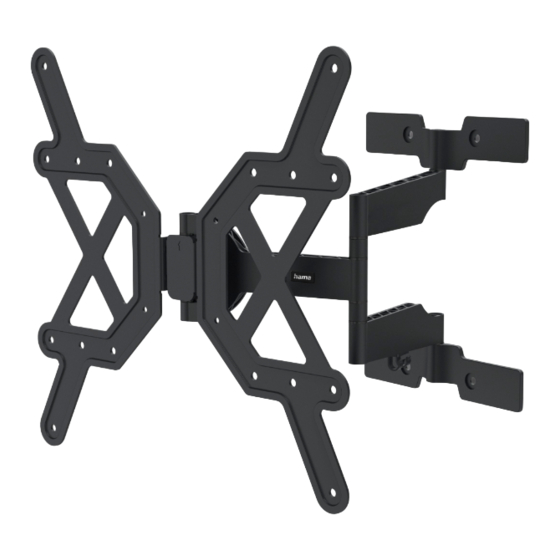
9. Technical data Maximum load: 30 kg Screen diagonal: 81.0 - 165.0 cm (US: 32" - 65") Depth: 5.6 cm - 41.6 cm Tilt: - /+ 6° (depending on device) Swivel range: Up to 180° (depending on device) at 3 joints Dimensions of the wall mounting plate: 24.0 x 30.1 cm Compliant with VESA standard:... -
Page 17: Warranty Disclaimer
In the event of a warranty claim, please contact us at Hama GmbH & Co KG, Dresdner Str. 9, 86653 Monheim, Germany, enclosing proof of purchase. You are also welcome to contact us at www.hama.de or by phone on...
Need help?
Do you have a question about the 00 220849 and is the answer not in the manual?
Questions and answers