Advertisement
The Model CB60 provides a means for quick connection of certain
Xantech IR Receivers, such as the 490-30, to up to six emitters and
a power supply. It can also provide a low cost means of easy emitter
expansion for existing systems or to connect multiple emitters at the
output of other Xantech devices, such as the 590 Programmable
Controller, the 710 Fone Link, 792-10 Power Module and certain
connecting blocks, such as the CB12 and the 791-44.
SPECIFICATIONS
• IR Receiver Input: 3.5mm stereo mini phone jack.
• Outputs: 6 emitter ports (3.5mm mono mini type phone jacks) in a parallel hook-up.
• Contains a 100 Ohm resistor in series with each emitter output.
• 282, 283, 284, 284-10, and 286 mini-emitters may be used.
• Power requirements: 12 volts DC. Uses 781RG or 782 Power Supplies. Note: A power supply is not
used when the CB60 is used solely as an emitter expander.
• 2.1 mm coaxial power jack.
• Dimensions: 2-15/16" W x 1-3/4" D x 13/16" H
INSTALLATION
The following diagram, Fig. 2, illustrates the primary use of the CB60; to connect a Xantech IR Receiver,
equipped with a 3.5 mm stereo mini plug, into an IR controlled system. In this case a 490-30 is shown
plugged into the "IR Receiver" jack on the CB60.
Note that everything is quick connect; the IR receiver, the power supply and the emitters. (Since the emitter
ports are connected in parallel within the CB60, you may plug in the 283M's in any order). The 490-30 &
CB60 are intended for use in installations where the connecting block is within reach of the 7-foot cable on
the 490-30 -- such as when installing the 490-30 in a cabinet where the controlled equipment is behind
closed doors.
The Mini-Emitters, any of the 282, 284, 283 &
286 series, may be affixed directly over the
infrared window of the controlled device, us-
ing the clear adhesive layer on the flat surface
of the emitter. In some applications, it may be
desirable to affix the flat surface of the 282M
higher output emitters to a cabinet door, side
or shelf with the rounded surface aimed at the
infrared window. Maximum output from the
282M comes from the rounded surface oppo-
site the adhesive layer.
INSTALLATION INSTRUCTIONS
CB60
CONNECTING BLOCK
Hand Held
Remote
Controlled Equipment
(mounted behind
closed cabinet doors)
Fig. 2 A Typical CB60/490-30 IR System
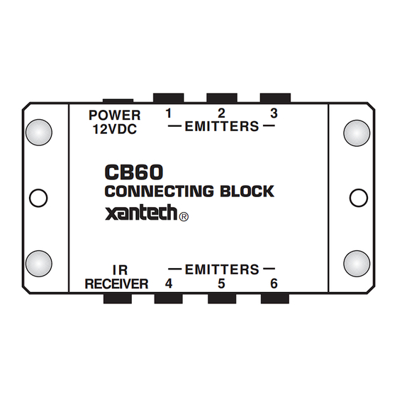
POWER
12VDC
RECEIVER
Fig. 1 Model CB60 Connecting Block
490-30
Series
Micro Link
CB60
IR Receivers
Connecting Block
(mounted on
or near
cabinet in an
inconspicuous
location).
7 Foot
3-Conductor
Cable with
Quick Connect
Mini Plug
1
2
3
EMITTERS
CB60
CONNECTING BLOCK
®
I R
EMITTERS
4
5
6
781RG
Satellite Receiver
Power Supply
To 120 V AC
(Unswitched)
283M
Blink IR™
VCR
283M
Blink IR™
AV Receiver
283M
Blink IR™
CD Changer
283M
Blink IR™
Cassette DecK
283M
Blink IR™
Mouse Emitter
1
Advertisement
Table of Contents

Subscribe to Our Youtube Channel
Related Manuals for Xantech CB60


Summary of Contents for Xantech CB60
- Page 1 Note that everything is quick connect; the IR receiver, the power supply and the emitters. (Since the emitter ports are connected in parallel within the CB60, you may plug in the 283M's in any order). The 490-30 & CB60 are intended for use in installations where the connecting block is within reach of the 7-foot cable on the 490-30 -- such as when installing the 490-30 in a cabinet where the controlled equipment is behind closed doors.
- Page 2 In these cases, use the appropri- ate mono mini plug cable, such as the Xantech part #6017400 (3.5 mm to 3.5 mm) or #6015900 (3.5 mm to stripped bare wire ends), to interface between the output port of these devices and the "IR Receiver" input port of the CB60.
Need help?
Do you have a question about the CB60 and is the answer not in the manual?
Questions and answers