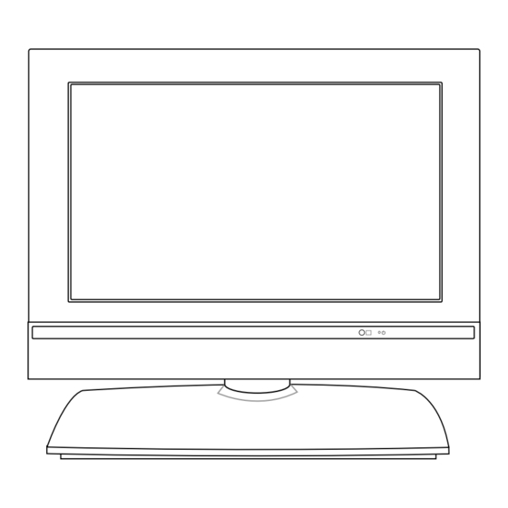
Summary of Contents for LG RZ-17LZ40
- Page 1 LCD TV SERVICE MANUAL CHASSIS : ML-024F MODEL : RZ-17LZ40 CAUTION BEFORE SERVICING THE CHASSIS, READ THE SAFETY PRECAUTIONS IN THIS MANUAL.
-
Page 2: Table Of Contents
CONTENTS Contents ....................2 Safety Precautions ..................3 Servicing Precautions ................4 Specifications ..................6 Description of Controls ................8 Adjustment Instruction ................11 Block Diagram ..................17 Exploded View ..................18 Exploded View Parts List ...............19 Replacement Parts List ................ 20 SVC. Sheet .................... -
Page 3: Safety Precautions
SAFETY PRECAUTIONS IMPORTANT SAFETY NOTICE Many electrical and mechanical parts in this chassis have special safety-related characteristics. These parts are identified by in the Schematic Diagram and Replacement Parts List. It is essential that these special safety parts should be replaced with the same components as recommended in this manual to prevent X-RADIATION, Shock, Fire, or other Hazards. -
Page 4: Servicing Precautions
SERVICING PRECAUTIONS CAUTION: Before servicing receivers covered by this service damage caused by static by static electricity. manual and its supplements and addenda, read and follow the 1. Immediately before handling any semiconductor component or SAFETY PRECAUTIONS on page 3 of this publication. semiconductor-equipped assembly, drain off any electrostatic NOTE: If unforeseen circumstances create conflict between the charge on your body by touching a known earth ground. - Page 5 c. Quickly move the soldering iron tip to the junction of the Fuse and Conventional Resistor component lead and the printed circuit foil, and hold it there Removal/Replacement only until the solder flows onto and around both the 1. Clip each fuse or resistor lead at top of the circuit board hollow component lead and the foil.
-
Page 6: Specifications
5°C) (1) Capacity: Follow LG electronics TV Testing Standard. (2) Humidity: 65% ± 10% (2) RCA JACK performance :Follow the standard of LG. (3) Power: Standard input voltage (AC 100-220V, 50/60Hz) (3) Another Required Standard (4) Measurement must be performed after heat-run more than Follow the standard of each nation. - Page 7 5. Feature and Function Specification Item Remark Unit Teletext TOP(option) TOP,FLOF,LIST REMOCON NEC code RGB(VGA) input D-Sub 15 pin Rear Component input Option, Non-EU Y, P PERI TV Connector Option, EU Rear (Full Scart) AV input Rear S-video input Rear RS232 Port Only for RMS Rear...
-
Page 8: Description Of Controls
DESCRIPTION OF CONTROLS All the functions can be controlled with the remote control handset. Some functions can also be adjusted with the buttons on the side panel of the set. Only the remote control handset supplied will operate this set. Remote control handset Before you use the remote control handset, please install the bat- teries. - Page 9 10. TV/PC selects TV or PC mode. clears the menu from the screen. switches the set on from standby. 11. POWER switches the set on from standby or off to standby. MUTE POWER 12. I/II selects the language during dual language broadcast. TV/PC TV/AV I/II...
- Page 10 • RZ-17LZ40 series Top panel ON/OFF TV/AV/PC MENU Side panel • RZ-15LA70 series S-VIDEO VIDEO (MONO) AUDIO Back panel • RZ-15LA66 series MONO DUAL STEREO 1. ON/OFF 7. POWER/STANDBY INDICATOR (r r ) switches the set on from standby or off to illuminates red in standby mode.
-
Page 11: Adjustment Instruction
ADJUSTMENT INSTRUCTION 1. Application Object (8) At this time the adjustment starts automatically changing the number in order of RO --> GO --> BO --> RD --> GD -- This instruction is for the application to the LCD TV/Monitor, > BD. ML-024F. - Page 12 5. Option1 data(200PR~A2 ST:1bit,SYS:2bit) OPTION I/II OPTION I/II TEXT SCART TEXT SCART 200PR 200PR SAVE STER SAVE STER Data Data...
- Page 13 OPTION OPTION TEXT I/II SV SCART A2 ST TEXT I/II SV SCART A2 ST 200PR 200PR Data Data...
- Page 14 OPTION OPTION TEXT I/II SV SCART A2 ST TEXT I/II SV SCART A2 ST 200PR 200PR Data Data...
- Page 15 OPTION TEXT I/II SV SCART A2 ST 200PR Data 6. Option2 data(ACMS~BBACK:1bit,LANG:3bit) Data ACMS BBACK LANG Data ACMS BBACK LANG...
- Page 16 7. Option3 data(IIC AFT~CH+AU:1bit) OPTION IIC T MONO CH+AUS HiDEV Data...
-
Page 17: Block Diagram
BLOCK DIAGRAM... -
Page 18: Exploded View
EXPLODED VIEW... -
Page 19: Exploded View Parts List
METAL,BASE EGI 17LZ40 4950V00194A METAL,STAND SPCC(CR) SUPPORTER(LA70) 3809V00427B BACK COVER ASSEMBLY,RZ-17LZ40 1SCART 1PHONE C/SKD 3809V00427C BACK COVER ASSEMBLY,RZ-17LZ40 1SCART 1PHONE C/SKD 412-36D 3550V00335C COVER,REAR AV RU-17LZ22 ABS, HF-380 SKD 6871VMMR43A PWB(PCB) ASSEMBLY,MAIN ML-024F RZ-17LZ40(PCB ASSY MAIN) 4950V00168F METAL,SHIELD EGI 0.8T ML-024F C/SKD... -
Page 20: Replacement Parts List
REPLACEMENT PARTS LIST For Capacitor & Resistors, the CC, CX, CK, CN : Ceramic RD : Carbon Film charactors at 2nd and 3rd digit CQ : Polyestor RS : Metal Oxide Film in the P/No. means as follows; CE : Electrolytic RN : Metal Film RF : Fusible LOCA. - Page 21 For Capacitor & Resistors, the CC, CX, CK, CN : Ceramic RD : Carbon Film charactors at 2nd and 3rd digit CQ : Polyestor RS : Metal Oxide Film in the P/No. means as follows; CE : Electrolytic RN : Metal Film RF : Fusible LOCA.
- Page 22 For Capacitor & Resistors, the CC, CX, CK, CN : Ceramic RD : Carbon Film charactors at 2nd and 3rd digit CQ : Polyestor RS : Metal Oxide Film in the P/No. means as follows; CE : Electrolytic RN : Metal Film RF : Fusible LOCA.
- Page 23 LOCA. NO PART NO DESCRIPTION LOCA. NO PART NO DESCRIPTION L704 6210TCE001G FILTER,HH-1M3216-501 CERATEC 3216MM L801 6210TCE001G FILTER,HH-1M3216-501 CERATEC 3216MM L802 6210TCE001G FILTER,HH-1M3216-501 CERATEC 3216MM L803 6210TCE001G FILTER,HH-1M3216-501 CERATEC 3216MM 6210TCE001G FILTER,HH-1M3216-501 CERATEC 3216MM LF701 6200JB8012Q FILTER,OR 14*7*7.5H SMC BK 6.0-11.0MH 0.55PHY R226 6200JB8010L FILTER,MLB-201209-1000L-N2 MAG LAYERS...
- Page 25 PRINTED CIRCUIT BOARD MAIN(TOP) MAIN(BOTTOM) POWER CONTROL...
- Page 26 Dec, 2003 P/NO : 3828VD0168M Printed in Korea...


Need help?
Do you have a question about the RZ-17LZ40 and is the answer not in the manual?
Questions and answers