Subscribe to Our Youtube Channel
Summary of Contents for LG RZ-15LA32
-
Page 1: Service Manual
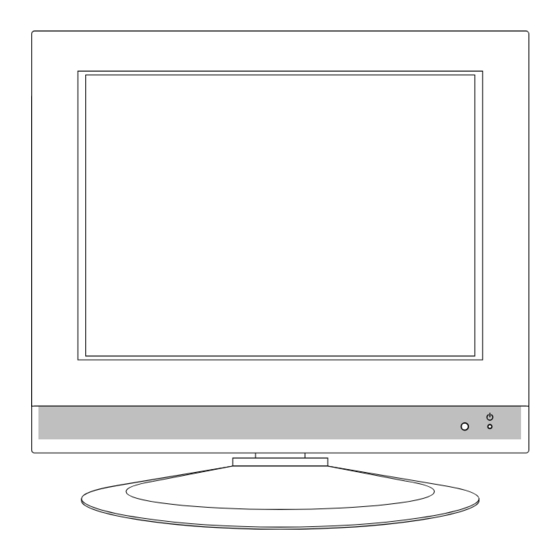
LCD TV SERVICE MANUAL CHASSIS : ML-024A MODEL : RZ-15LA32 CAUTION BEFORE SERVICING THE CHASSIS, READ THE SAFETY PRECAUTIONS IN THIS MANUAL. -
Page 2: Table Of Contents
CONTENTS Contents ....................2 Safety Precautions ..................3 Servicing Precautions ................4 Specifications ..................6 Description of Controls ................8 Adjustment Instruction ................11 Block Diagram ..................13 Exploded View ..................14 Exploded View Parts List ...............15 Replacement Parts List ................ 16 SVC. Sheet ....................- 2 -... -
Page 3: Safety Precautions
SAFETY PRECAUTIONS IMPORT ANT SAFETY NOTICE Many electrical and mechanical parts in this chassis have special safety-related characteristics. These parts are identified by the Schematic Diagram and Replacement Parts List. It is essential that these special safety parts should be replaced with the same components as recommended in this manual to prevent X-RADIATION, Shock, Fire, or other Hazards. -
Page 4: Servicing Precautions
SERVICING PRECAUTIONS CAUTION: Before servicing receivers covered by this service transistors and semiconductor "chip" components. The manual and its supplements and addenda, read and follow the following techniques should be used to help reduce the SAFETY PRECAUTIONS on page 3 of this publication. incidence of component damage caused by static by static NOTE: If unforeseen circumstances create conflict between the electricity. - Page 5 c. Quickly move the soldering iron tip to the junction of the Fuse and Conventional Resistor component lead and the printed circuit foil, and hold it Removal/Replacement there only until the solder flows onto and around both the 1. Clip each fuse or resistor lead at top of the circuit board component lead and the foil.
-
Page 6: Specifications
SPECIFICATIONS Note : Specification and others are subject to change without notice for improvement. Receivable Broadcasting system: Feature & Funtion PAL-B/G, D/K, I AV Input : 1(Rear) SECAM S-Video Input : 1(Rear) NTSC M Component Input-option H/P Output : 1(Rear) RF Input Channel: RGB(VGA) INput : 1(D-sub 15 pin) VHF : E2 ~ E12... - Page 7 Displayable Monitor Output Format Specifications Horizontal Vertical MODE Resolution Frequency (KHz) Frequency (Hz) 640x400 37.9KHz 85Hz 640x480 31.5KHz 60Hz 640x480 35.0KHz 67Hz 640x480 37.9KHz 72Hz 640x480 37.5KHz 75Hz 640x480 43.3KHz 85Hz 800x600 35.2KHz 56Hz 800x600 37.9KHz 60Hz SVGA 800x600 48.1KHz 72Hz 800x600 46.9KHz...
-
Page 8: Description Of Controls
DESCRIPTION OF CONTROLS All the functions can be controlled with the remote control handset. Some functions can also be adjusted with the buttons on the side panel of the set. Only the remote control handset supplied will operate this set. Remote control handset POWER MUTE... - Page 9 8. MUTE switches the sound on or off. 9. TV/AV/PC selects TV, AV or PC monitor mode. clears the menu from the screen. switches the set on from standby. POWER MUTE 10. SLEEP sets the sleep timer. 11. LIST displays the programme table. 12.
-
Page 10: Side Panel
Side panel Back panel S-VIDEO VIDEO (MONO) AUDIO 1. MAIN POWER (ON/OFF) 7. POWER/STANDBY INDICATOR (r r ) switches the set on or off. illuminates brightly when the set is in standby mode. 2. TV/AV/PC dims when the set is switched on. selects TV, AV or PC monitor mode. -
Page 11: Adjustment Instruction
ADJUSTMENT INSTRUCTION 1. Application Object 3-2. Preparation for Adjustment (1) Perform ‘Heat Run’ for more than 15 minutes in white This instruction is for the application to the LCD TV/Monitor, pattern. ML-024A. (2) Connect the signal of pattern generator with LCD TV of PC Input Jack(D-Sub). - Page 12 4. Position of Mode Adjustment Timing of Mode Table * H[dot]/V[line] VGA-85 SVGA-56 SVGA-60 SVGA-72 SVGA-75 Mode VGA-60 VGA-67 VGA-72 VGA-75 1056 H_Total 1024 1056 1040 H_Display H_Blanking H_Sync H Polarity NEG. NEG. NEG. NEG. NEG. H_Bp H_Fp 46.875 H-Freq[KHz] 31.469 35.0 37.861...
-
Page 13: Block Diagram
BLOCK DIAGRAM - 13 -... -
Page 14: Exploded View
EXPLODED VIEW P801 - 14 -... -
Page 15: Exploded View Parts List
EXPLODED VIEW PARTS LIST PART NO. DESCRIPTION 6304FLP006C LCD MODULE,LC151X01-C3M2 LG PHILPS TFT COLOR NON 6400VA0017A SPEAKER,T401SX-095K14 LG C&D 8 OHM 1.0/1.5W 81DB 4950V00067A METAL,SUPPORTER EGI SPEAKER HOLDER 3091V00A15L CABINET ASSEMBLY,NON ML012A FLATRON 5020V00552F BUTTON,CONTROLABS, HF-380 7KEY #155 5020V00553D BUTTON,POWER NON 1 KEY SET... -
Page 16: Replacement Parts List
REPLACEMENT PARTS LIST LOCA. NO PART NO DESCRIPTION LOCA. NO PART NO DESCRIPTION D706 0DR060009AA DIODE,RECTIFIERS TVR06J TP DO41 600V 0.6A D707 0DRSD00091A DIODE,RECTIFIERS SF20JC10 100V 20A 200A .SEC 0.7MA 0IMCRTH001A THC63LVDM83R THINE ELECTRONICS 56P D709 0DRSD00091A DIODE,RECTIFIERS SF20JC10 100V 20A 200A .SEC 0.7MA IC100 0IZZVC0047A INFINEON 52PIN - MICOM PAL... - Page 17 For Capacitor & Resistors, the CC, CX, CK, CN : Ceramic RD : Carbon Film charactors at 2nd and 3rd digit CQ : Polyestor RS : Metal Oxide Film in the P/No. means as follows; CE : Electrolytic RN : Metal Film RF : Fusible LOCA.
- Page 18 140-275B SWITCH,PUSH JDPB21NA EVLAND NON 30V 0.3A L401 0LA0272K139 INDUCTOR,AXIAL LEAD 27UH K 4X10.5 TP SW1101 140-313A SWITCH,TACT 2LEAD 100G(TA) LG C&D NON 5V 6140VR0004A COIL,ENERGY RECOVERY TOKO B953AS-330M=P3, 33UH SW1102 140-313A SWITCH,TACT 2LEAD 100G(TA) LG C&D NON 5V 6140VR0004A...
- Page 19 TU401 6700PF0002A TUNER,TAFH-S321D LG PAL FS 4SYS VA701 164-003K VARISTOR,SVC621D-14A ILJIN 620V 0% UL/CSA/VDE BK ACCESSORIES 3828VA0381B MANUAL,OWNERS ML024A DG/BN LG GE/FR/NE/EN 082R 3828VA0381H MANUAL,OWNERS ML024A STUH/E2000 LG GE/FR 6710V00082R REMOTE CONTROLLER ML024A TXT RZ-15LA32 NEC CODE - 19 -...
-
Page 20: Svc. Sheet
SVC. SHEET : 3854V A0107A-S... - Page 21 P/No : 3854VA0107A-S(1/2) 2002.12.11...
-
Page 22: Power
MAIN(TOP) MAIN(BOTTOM) CONTROL POWER P/No : 3854VA0107A-S(2/2) 2002.12.11... - Page 23 Dec., 2002 P/NO : 3828VD0131H Printed in Korea...


Need help?
Do you have a question about the RZ-15LA32 and is the answer not in the manual?
Questions and answers