Table of Contents
Advertisement
Quick Links
Advertisement
Table of Contents
Troubleshooting

Related Manuals for ubiquoss U9016B


Summary of Contents for ubiquoss U9016B
- Page 1 U9016B For GPON Installation Guide...
- Page 2 U9016B Installation Guide UbiQuoss Inc. 24F Millennium B/D, 467-12 Dogok-Dong Gangnam-Gu, Seoul 135-700 Korea TEL: +82-70-8666-5000 FAX: +82-2-2190-3201 E-mail: oversea.team@ubiQuoss.com www.ubiQuoss.com...
- Page 3 It describes how to install U9016B and connection it to other devices. Chapter 1 describes the name and function of each part of U9016B and Chapter 2 describes the necessary items and notes for the installation. The user is recommended to understand U9016B and remember notes through Chapter 1 before the installation because it will be very useful for the user to install and use U9016B safely.
- Page 4 Preface Description of Symbols The installation guide uses the following icons and fonts to indicate special messages for the reader. Note Presents the useful contents related to the user guide, the references and data related to the product use, etc. Caution Describes the situation that data loss and incorrect product operation can occur, and provides the proper actions to take in the situation.
- Page 5 Chapter 3. Installation This chapter describes how to install U9016B onto a rack and connect each port of the device. Chapter 4. Troubleshooting This chapter describes the problems that can occur during the installation and use of U9016B and how to resolve them.
-
Page 6: Table Of Contents
Overview ........................2 Main Function and Features ..................... 2 Features ......................... 3 Front Panel ........................3 Description on each U9016B unit ..................3 LED for each U9016B unit ....................4 Fan Ventilation ........................5 Power Supply ........................6 Ground Terminal ....................... 6 Chapter 2. - Page 7 Layer 3 Features ........................30 QoS Features........................30 Security Features ......................... 30 System Security Features ...................... 31 System Information ......................31 Appendix B. Cable Spec ................33 Ethernet cable ......................... 34 Optical cable ........................34 Console cable ......................... 35 U9016B Installation Guide...
-
Page 8: List Of Table
List of Tables List of Tables Table 1 Description on each U9016B unit ..............3 Table 2 LED for each U9016B unit ................4 Table 3 List of items necessary for Installation ............11 Table 4 List of Package Items ................12 Table 5 Console Cable Pin Signal ................. - Page 9 Figure 4. Rear and Side ................... 5 Figure 5. Installing the LINE Card ................16 Figure 5. Unistalling the LINE Card ............... 17 Figure 5. U9016B AC Connecting Power .............. 18 Figure 6. U9016B DC Connecting Power .............. 18 Figure 7. Connecting Console Terminal ..............20 Figure 8.
- Page 10 List of Figures Introduction...
-
Page 11: Chapter 1. Introduction
Chapter 1. Introduction This chapter introduces the product types and features of U9016B and the name and function of each part as well. The chapter consists of the followings: Overview Features U9016B Installation Guide... -
Page 12: Overview
2.5G/upstream 1.25G GPON optical line service. In addition, U9016B provides 1G sfp 4 ports and 10g sfp+ 2 ports for uplink to connect to the Ethernet network. The PON Line Card is a modular type, giving flexibility in numbers of subscribers to be accommodated and bandwidth to be allocated the subscribers. -
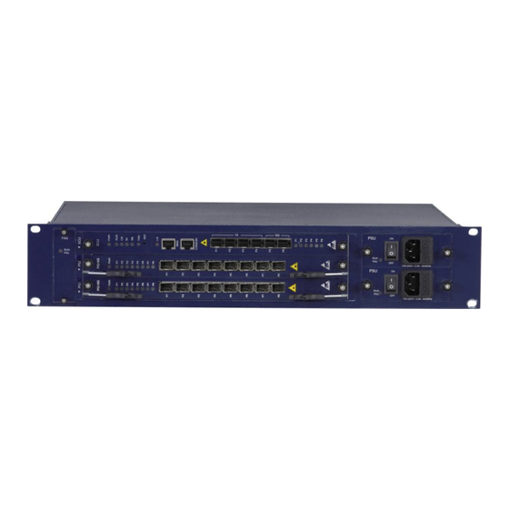
Page 13: Features
Braket Braket AC Power Figure 1. Front Panel Unit Description on each U9016B unit Table 1 Description on each U9016B unit Unit Description Remarks System Management Block and Switch Configuration Unit. Common part AC 100–240 VAC, 50/60Hz Power Module: Supporting... -
Page 14: Led For Each U9016B Unit
Features LED for each U9016B unit Table 2 LED for each U9016B unit Unit Status Description GREEN Power ON ORANGE Reset or Power Fail System Critical Alarm ON System Critical Alarm OFF System Major Alarm ON ORANGE System Major Alarm OFF... -
Page 15: Fan Ventilation
Figure 4. Rear and Side Caution U9016B has the structure that the Fan Module (FMU) is located on the side of the device. Consequently, if the left side and the right side of the device are blocked, the internal warm air and the external cold air cannot be circulated properly and the product can be overheated. -
Page 16: Power Supply
Features Power Supply U9016B uses AC or DC to supply power to the system, and it provides two terminals that provide power to the system for power redundancy as shown below. The power switch is used to turn on or off the power supply. If the power supply is out of order, set the power switch of the applicable power supply to OFF (O direction) before replacing the power supply. -
Page 17: Chapter 2. Installation Preparation
Installation Preparation This chapter explains about the items necessary to install U9016B and notes for installing and using the product. The user should fully understand the notes in this chapter before installing the product to prevent any problem that may occur during the installation of product. -
Page 18: Notes To Take Before Installation
Notes to Take before Installation Notes to Take before Installation Before installing and using U9016B, the user should fully understand the warnings and notes explained in this section and follow the instructions. Do not disassemble the product The user should not disassemble the product. If the user thinks that a repair is necessary, contact the ubiQuoss Technical Support Team. -
Page 19: Grounding
Checking a rack before installation In case of installing U9016B on rack, check the stability of the rack first to prevent from occurrence of the case that the rack falls down or fails to hold the product weight after the product is installed. -
Page 20: Other Notes
Checking the installation environment This section describes the necessary installation environment to install and use U9016B safely. It is recommended to keep the U9016B temperature and humidity stable. The product can be used in the following environment: Operating temperature: 0~50°C ... -
Page 21: Necessary Items For Installation
Necessary Items for Installation An U9016B installation requires the items described below. The items marked by * are not supplied with the product. The user should prepare these before the product installation. Table 3 List of items necessary for Installation ... -
Page 22: Package Items
Package Items Package Items The U9016B package includes the followings: Table 4 List of Package Items Items Quantity Usage 1 EA U9016B Body Body The manual that describes how to install the device and connect cables Hardware Installation Guide or... -
Page 23: Chapter 3. Installation
Chapter 3. Installation This chapter describes how to install U9016B onto a rack and connect each port of the device. The chapter consists of the following sections: Selecting an Installation Site Installation onto a Rack Connecting Power ... -
Page 24: Selecting Installation Place
Selecting Installation Place Selecting Installation Place To install and use U9016B safely, it should be installed in the environment that satisfies the following conditions: Avoid the location whose temperature is too high or low. (Especially, avoid the location that is exposed to direct sunrays or the location around a heater.) ... -
Page 25: Mounting On A Rack
Mounting on a Rack U9016B can be mounted onto a standard 19” rack. The following describes how to install U9016B onto a rack: 1. Remove all the cables connected to the product and turn off the power. 2. Put the product on the floor or a firm table that is near the installation rack. -
Page 26: Installing Line Card
Installing LINE Card Installing LINE Card 1. Insert LINE Card in the chassis rail. 2. Hang the each side hinge of ejector at the hanging pin. 3. Press the lever with fingers and push it forward powerfully. 4. When the hinges of ejectors are inserted in the holes, the LINE card is installed on the backplane socket well. -
Page 27: Uninstalling The Line Card
2. Pull out the each side hinge of ejector from the hanging pin of a chassis. 3. Take the end of ejector lever and pull it backward powerfully. 4. While the ejectors unfold more, the LINE Card is separated from the backplane socket. Figure 6. Unistalling the LINE Card U9016B Installation Guide... -
Page 28: Connecting Power
Connecting Power Connecting Power Before connecting power to U9016B, make sure the power switches on the rear side of the product are set to OFF. AC power: Connect a power cable accompanying the product to a power input terminal and then connect the plug of the power cable to the grounded AC power outlet. - Page 29 Caution The power for the U9016B using AC should satisfy the following specifications: Input Voltage: 100-240 VAC Power consumption: Max 160 Watt (– based on full installation Input frequency: 50/60Hz The power for the U9016B using DC should satisfy the following specifications: ...
-
Page 30: Connecting Console Terminal
Connecting Console Terminal Connecting Console Terminal U9016B can be set or monitored through a local console port. The use of console cable that came with the product is recommended to connect between the product and the console terminal. Connect the RJ-45 connector of console cable to the console port of the product and the DB-9 connector (the other side of the cable) to the console terminal. -
Page 31: Connecting Management Port
Connecting Management Port U9016B provides an Ethernet port so that the user can manage the product through the host connected to a local network. Use the Ethernet cable (UTP Category 5) accompanying the product for the connection of the management Ethernet port to the network. Connect one RJ-45 connector of the Ethernet cable to the management Ethernet port and the other connector to the device such as the switch connected to the network. -
Page 32: Operation Checking
In case that a console terminal is connected after the device initialization is completed, the user can see the login message by pressing [Enter]. Note For how to set the device after the login through CLI, see the U9016B User Guide accompanying this Hardware Installation Guide. Note... - Page 33 U9016B (config-if-eth0)#end 9. To view the IP address previously set, the mode should be changed to root mode. 10. In a U9016B# prompt, please use the following command to check the current IP address U9016B# show ip interfaces brief 11. After checking if the IP address is correct set, please use the following command to save the IP address in the system.
- Page 34 Operation Checking Installation...
-
Page 35: Chapter 4. Troubleshooting
If the device fails to operate normally, see the description in this chapter and check if the problem can be resolved. If the user thinks that the problem is too difficult, contact the Technical Support Team of ubiQuoss Inc., and the team will take proper actions promptly. U9016B Installation Guide... -
Page 36: Troubleshooting Case
Troubleshooting Case Troubleshooting Case [Problem 1] The Power LED is not turned on. The power is not supplied normally. Solution Check if the power cable is properly connected to the power input terminal and the outlet. Check the power supplying status of the outlet that the power cable is connected to. - Page 37 Check if the connector of the cable is inserted into the port properly. Check if the connected device is operating normally. Check if the cable used for the port satisfies the specifications in Appendix B. U9016B Installation Guide...
- Page 38 Troubleshooting Case Troubleshooting...
-
Page 39: Appendix A. Product Spec
Appendix A. Product Spec Appendix A describes the product specifications of U9016B. Overview 19” Rack mountable Shelf structure 3 Card Slots Hot Swappable Cards 1G x 4PORT(SFP), 10G x 2PORT(SFP+) 2.5G GPON 8 PORT ... -
Page 40: Layer 3 Features
Troubleshooting Case Layer 3 Features Items Description Static Routing RIP, OSPF, BGP Default Gateway Routing VRRP ECMP Max 8 paths PBR (Policy Based Routing) PIM-SM, IGMP v2 Multicast Max 1K Group Support DHCP Server/Relay DHCP Blocking of illegal IP users DAI (Dynamic ARP Inspection) QoS Features Items... -
Page 41: System Security Features
PSBP & PON OLT system Back Board assembly Chassis PSU-AC PON OLT system Power Unit -AC PSU-DC PON OLT system Power Unit -DC FMU-P PON OLT system FAN Module ( 3 FAN / 1 Module ) U9016B Installation Guide... - Page 42 Troubleshooting Case Troubleshooting...
-
Page 43: Appendix B. Cable Spec
Appendix B. Cable Spec Appendix B describes the specifications of the cable used to connect the ports of U9016B. Appendix B consists of: Ethernet cable Optical cable Console cable U9016B Installation Guide... -
Page 44: Ethernet Cable
Troubleshooting Case Ethernet cable In case of connecting the management Ethernet port on the front of U9016B, use the UTP cable that has RJ-45 connectors on both sides. In case of using a twisted-pair cable, choose the one of a proper category, depending on the device speed. -
Page 45: Console Cable
The table below describes the types of the signals transmitted from each pin of the connectors on both sides of a console cable. Table 5 Console Cable Pin Signal Pin No. Pin No. Signal Pin Definition (Console Port) (Console Terminal) Transmit Data Receive Data U9016B Installation Guide... - Page 46 Troubleshooting Case Troubleshooting...
Need help?
Do you have a question about the U9016B and is the answer not in the manual?
Questions and answers