Table of Contents
Advertisement
Quick Links
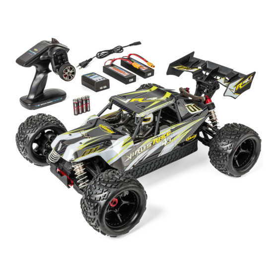
Virus Race 4.3 4S Brushless
ASSEMBLED READY-TO-RUN MODEL
Achtung - Attention - Attention
Attenzione - Atención - Pas op
DE // Betriebsanleitung
GB // Instruction Manual
FR // Avertissement de sécurité
IT // Avvertenze di sicurezza
ES // Indicaciones de seguridad
NL // Veiligheidsinstructies
Montageanleitung - Instructions
Ersatzteile - Spare Parts
500409086 / 500409087 // Stand: November 2023
02
03 - 16
17 - 30
31 - 33
34 - 36
37 - 39
40 - 42
43
62
Advertisement
Chapters
Table of Contents
Troubleshooting

Related Manuals for Carson Virus Race 4.3 4S Brushless


Summary of Contents for Carson Virus Race 4.3 4S Brushless
- Page 1 Virus Race 4.3 4S Brushless ASSEMBLED READY-TO-RUN MODEL Achtung - Attention - Attention Attenzione - Atención - Pas op DE // Betriebsanleitung 03 - 16 GB // Instruction Manual 17 - 30 FR // Avertissement de sécurité 31 - 33...
- Page 2 Handbuch enthält die technischen Anlagen, wichtige Den aktuellsten Stand ihres Handbuches finden sie unter: Anleitungen zur korrekten Inbetriebnahme und Nutzung sowie www.carson-modelsport.com Produktinformation entsprechend dem aktuellen Stand vor der GB // Important information Before using your product for the first time or ordering any spare date before going to press.
-
Page 3: Vorwort
Ansprüche abgeleitet werden. Garantiebedingungen Von der Garantie ausgeschlossen sind: Für dieses Produkt leistet CARSON eine Garantie von 24 Monaten • Beschädigung oder Ausfall durch Nichtbeachten der Sicher- betreffend Fehler bei der Herstellung in Bezug auf Material und heitsanweisungen oder der Bedienungsanleitung, höhere... -
Page 4: Table Of Contents
INHALT Vorwort ........................3 Fahrregler - Eigenschaften ................11 Lieferumfang Zubehör ..................4 Fahrregler - Anschluss/Verkabelung ............11 Sicherheitsanweisungen .................5 Fahrregler - Grundeinstellungen ..............12 Sicherheitsanweisungen Lithium Akkus ...........6 Erklärung des Gashebelbereichs ..............13 Chassis ........................7 Programmieren des Fahrreglers ..............14 Abnehmen der Karosserie ................7 Programmieren des Fahrreglers mit der SET-Taste ......15 Aufladen des Fahrakkus..................8 Anschluss der Programmierbox .............. -
Page 5: Sicherheitsanweisungen
SICHERHEITSANWEISUNGEN Sicherheitsanweisung und bestimmungsgemäße Verwendung Dieses Produkt ist ausschließlich für Hobbyzwecke ausgelegt und Bitte beachten sie, dass es bei verschiedenen Modellen zu erhöh- darf nur auf dafür vorgesehenen Plätzen benutzt werden. ten Geräuschpegeln kommen kann, daher dürfen diese nicht dauerhaft in ihrer unmittelbarer Umgebung betrieben werden. Mit diesen Modell dürfen keine Personen oder Tiere transportiert werden. -
Page 6: Sicherheitsanweisungen Lithium Akkus
• Akku während des Ladens und/oder Betriebs niemals Betriebshinweisen, sowie des Ersatzes des Akkus und dessen unbeaufsichtigt lassen. Wartung nicht möglich ist, kann Tamiya/Carson keinerlei Haftung für Verluste, Schäden oder Kosten übernehmen. • Unbedingt empfohlene Lade-/Entladeströme einhalten. Jeglicher Anspruch auf Schadenersatz, der sich durch den Betrieb, •... -
Page 7: Chassis
CHASSIS Fahrregler Spoiler Hintere Stoßdämpfer Motor Lenkservo Vorderreifen Hinterreifen Schalter EIN / AUS Chassis Vorderer Stoßdämpfer ABNEHMEN DER KAROSSERIE • Karosseriesplint entfernen • Karosserie aufklappen 7 // DE... -
Page 8: Aufladen Des Fahrakkus
AUFLADEN DES FAHRAKKUS ACHTUNG! Verwenden Sie zum Laden des Lithium-Ionen Akkus nur das im Lieferumfang enthaltene Ladegerät. Bitte beachten Sie hierfür die Anleitung des Ladegerätes. EINLEGEN DER FAHRAKKUS 1 Legen Sie die Akkus ein. 2 Setzen Sie die Abdeckung auf und 3 Fixieren Sie mit den Klettband. -
Page 9: Einschalten Der Rc-Anlage
EINSCHALTEN DER RC-ANLAGE ACHTUNG! Immer zuerst den Sender und anschließend erst das Modell anschalten! 1 Schließen Sie die Fahrakkus an. 2 Schalten Sie den Empfänger ein. 3 Setzen Sie die Karosserie auf und sichern Sie diese mit den Karosseriesplinten. STEUERN DES MODELLS •... -
Page 10: Fehlersuche
FEHLERSUCHE Problem Ursache Lösung Das Modell fährt nicht Sender oder Empfänger sind nicht einge- Schalten sie den Sender oder Empfänger ein schaltet Polarität der Akkus oder Akkutyp sind falsch Prüfen Sie die Polarität und den Akkutyp Tauschen Sie die Batterien aus bzw. tau- Batterien/Akkus sind schwach oder ganz schen Sie die Akkus oder laden sie die Akkus entleert... -
Page 11: Fahrregler - Eigenschaften
FAHRREGLER - EIGENSCHAFTEN Dieser Fahrregler kann leicht für einen einfachen Betrieb einge- • Proportionale Bremsfunktion mit 4 Stufen maximaler Bremskraf- stellt werden. Beim Einschalten sucht er automatisch den Neutral- teinstellung, 8 Stufen für Drag-Bremskrafteinstellung. punkt. Nach Beendigung des automatischen Setups gibt der Motor •... -
Page 12: Fahrregler - Grundeinstellungen
FAHRREGLER - GRUNDEINSTELLUNGEN Einstellen des Gashebelbereichs (Kalibrie- 1) Verwenden Sie einen neuen Fahrregler rung) 2) Verwenden Sie einen neuen Sender 3) Ändern Sie die Einstellungen der Neutralposition des Hebels, Damit der Steuerbereich Ihres Fahrreglers dem Ihres Senders ent- die ATV- oder EPA-Parameter usw. spricht, müssen Sie ihn für die folgenden Fälle kalibrieren, da der Fahrregler anderenfalls nicht richtig funktionieren kann. -
Page 13: Erklärung Des Gashebelbereichs
Erster Klick Zweiter Klick Dritter Klick LED blinkt 1 Mal LED blinkt 2 Mal LED blinkt 3 Mal ERKLÄRUNG DES GASHEBELBEREICHS LED-Anzeige im normalen Betrieb • Im normalem Betrieb leuchtet weder die rote noch die grüne LED-Anzeige, wenn sich der Gashebel im neutralen Bereich befin- det. -
Page 14: Programmieren Des Fahrreglers
PROGRAMMIEREN DES FAHRREGLERS 1. Programmierbare Einstellungen (die kursiven Texte sind die Standardeinstellungen) Einstellungen für Dragster S4 Fahrregler Programmierbare Programmierbarer Wert Einstellung 1. Fahrmodus Vorwärts Vorwärts Vorwärts / Rück- / Rück- Bremse wärts mit wärts Bremse 2. Bremskraft bei Neutralstellung 10 % 20 % 40 % 60 %... -
Page 15: Programmieren Des Fahrreglers Mit Der Set-Taste
PROGRAMMIEREN DES FAHRREGLERS MIT DER SET-TASTE Dieses Flowchart zeigt, wie man den Dragster Hinweis: 4S Fahrregler programmiert. Während des Programmiervorgangs gibt der Motor neben der blinkenden LED auch gleichzeitig einen „Piep“-Ton aus. 15 // DE... -
Page 16: Anschluss Der Programmierbox
ANSCHLUSS DER PROGRAMMIERBOX • Lüfterkabel entfernen • Nach Abschluss der Programmierung Lüfter wieder anschließen!!! • Programmierbox mit Anschluss verbinden Externe Programmierung: Anschluss zur Verbindung einer Programmierbox (Art.-Nr. 500906143) FAHRREGLER - FEHLERSUCHE Fehler Mögliche Ursache Lösung Nach dem Einschalten funktioniert der Die Anschlüsse zwischen Akku und Fahrreg- Überprüfen Sie die Stecker. -
Page 17: Preface
• Damage caused by losing control of your model; CARSON will, at its option, unless otherwise provided by law: • Any repairs other than those provided by a CARSON authorised (a) Correct the defect by repairing the product without charging service facility;... -
Page 18: Included Items Accessories
CONTENTS Preface ........................17 ESC - Features ..................... 25 Included Items Accessories ................18 ESC - Connection/Cabling ................25 Safety Precautions ................... 19 ESC - Basic Settings ..................26 Safety Precautions lithium batteries ............20 Throttle Range Explanation ................. 27 Chassis ........................21 Program the ESC .................... -
Page 19: Safety Precautions
SAFETY PRECAUTIONS Safety Instructions and Intended Use This product is designed exclusively for hobby use and may only Please note that various models can generate very high noise be used on tracks and areas intended for this purpose. levels and should, therefore, not be operated in your immediate proximity. -
Page 20: Safety Precautions Lithium Batteries
Tamiya / Carson can accept no liability for loss, damage or costs incurred. • Do not fail to keep to the recommended charge/discharge current. Any claim for damages that may result from operation, failure or faulty operation or that is in any way related thereto will therefore •... -
Page 21: Chassis
CHASSIS Speed controller Spoiler Rear shock unit Motor Steering Servo Front tyre Rear tyre Switch ON / OFF Chassis Front shock unit REMOVING THE BODY • Remove hook pin • To remove the body - swing to open 21 // GB... -
Page 22: Charge Battery Pack
CHARGE BATTERY PACK Beware: For charging the battery, only use the recommended charger. Please follow the instructions of the charger for this. INSERTING THE DRIVE BATTERIES 1 Insert the batteries 2 Put the battery plate on it and 3 Fix it with the loop tape. Advice •... -
Page 23: Turn On The Rc System
TURN ON THE RC SYSTEM CAUTION! Always turn the transmitter´s power switch ON first! 1 Connect the rechargeable battery for the driving. 2 Switch on the receiver. 3 Put the body on and fix it with the body split pins. HOW TO CONTROL YOUR MODEL •... -
Page 24: Troubleshooting
TROUBLESHOOTING Problem Cause Correction Model doesn´t move Transmitter or chassis power switch is not Switch power on receiver or transmitter ”ON“ Polarity or battery type is wrong Check polarity and type of battery Batteries have run down Change batteries or charge them Loss of control Batteries have run down Change batteries or charge them... -
Page 25: Esc - Features
ESC - FEATURES This speed controller can easily be set for simple operation. After • Proportional brake function with 4 steps of maximum brake powering up, it automatically searches for the neutral point. At the force adjustment, 8 steps of drag brake force adjustment end of the automatic setup, the motor emits a do-re-mi sound to •... -
Page 26: Esc - Basic Settings
ESC - BASIC SETTINGS Throttle range setting (throttle range calibra- 1) Begin to use a new ESC tion) 2) Begin to use a new transmitter 3) Change the settings of neutral position of the throttle lever, the In order to make the ESC fit the throttle range of your transmitter, ATV or EPA parameters, etc. -
Page 27: Throttle Range Explanation
Click SET key Click SET key Click SET key Green LED flashes for 1 time Green LED flashes for 2 times Green LED flashes for 3 times THROTTLE RANGE EXPLANATION Alert tones • Alert tone input voltage abnormal: The ESC begins to check the input voltage when power on. -
Page 28: Program The Esc
PROGRAM THE ESC 1. Programmable items (the italics texts in the form are the default settings) Programmable items for Dragster 4S Programmable item Programmable value 1. Running mode Forward Forward/ Forward/ with backward back- brake with ward brake 2. Drag brake force in neutral 10 % 20 % 40 %... -
Page 29: Program The Esc With The Set Button
PROGRAM THE ESC WITH THE SET BUTTON The following is a flowchart sample for pro- Note: gramming the Dragster S6 controller. In the program process, when the LED is flashing, the motor will emit “Beep” tone at the same time. Press the SET key to choose Attention the programmable value, the... -
Page 30: Esc - Connecting Program Card
ESC - CONNECTING PROGRAM CARD • Remove the fan cable • After completing the programming, reconnect the fans !!! • Connect programming box with connection External Programming: Port for Connecting Program Card (No 500906143) ESC - TROUBLE SHOOTING Trouble Possible reason Solution After power on, motor doesn’t work The connections between battery pack and... - Page 31 Toutes les pièces et produits faisant l‘objet de remplacement • Des dommages esthétiques; deviennent la propriété de CARSON. Dans le cadre des prestations • Le transport, l’expédition et les frais d’assurance; et de garantie, seules des pièces neuves ou retraitées peuvent être •...
- Page 32 CONSIGNES DE SÉCURITÉ Consignes de sécurité et utilisation conforme Ce produit a été exclusivement conçu à des fins de loisir et ne doit niveau de bruit peut être élevé. Pour cette raison, veuillez ne pas être utilisé qu’à des endroits prévus à cet effet. les faire fonctionner de façon permanente auprès de vous.
- Page 33 • Respectez impérativement les courants de charge et de TAMIYA / CARSON refuse toute prise en charge des pertes, décharge recommandés. dommages et frais entraînés.
- Page 34 Pertanto, se il prodotto acquistato presenta lievi differenze Condizioni di Garanzia Dalla garanzia sono esclusi: CARSON offre una garanzia di 24 mesi, dalla data di acquisto • Danni o guasti derivanti dalla mancata osservanza delle presso qualsiasi rivenditore autorizzato, contro eventuali difetti di istruzioni d‘uso e di sicurezza, da cause di forza maggiore,...
- Page 35 ISTRUZIONI DI SICUREZZA Istruzioni di sicurezza e uso conforme Questo prodotto, progettato esclusivamente a scopo di svago, Dato che alcuni modelli possono raggiungere livelli di può essere impiegato unicamente in spazi appositamente rumore particolarmente elevati, si raccomanda di non tenerli previsti.
- Page 36 TAMIYA / CARSON declina ogni responsabilità • Rispettare scrupolosamente le correnti di caricamento/ legata a perdite, danni o costi.
- Page 37 • Daños derivados de la pérdida de control del producto CARSON, en función de su propio criterio, y si en la ley no se esta- • Reparaciones realizadas por un servicio no autorizado por...
- Page 38 INSTRUCCIONES DE SEGURIDAD Directiva de seguridad y uso conforme Este producto ha sido diseñado exclusivamente para fines de ocio niveles sonoros muy elevados, de ahí que estos no deban ser y solo debe ser usado en los lugares previstos para ello. utilizados de forma permanente cerca de su entorno.
- Page 39 TAMIYA / CARSON no puede asumir ningún tipo de responsabilidad por pérdidas, daños o costes. • Respetar siempre la corriente de carga/descarga recomendada.
- Page 40 Garantievoorwaarden Uitgesloten van de garantie zijn: CARSON verleent een garantie van 24 maanden op dit product in • Beschadiging of uitval door niet-naleving van de veiligheids- geval van fabricagefouten in het materiaal en vakmanschap bij...
- Page 41 VEILIGHEIDSINSTRUCTIES Veiligheidsinstructies en doelmatig gebruik Dit product is uitsluitend ontworpen voor hobbydoeleinden en produceren. Daarom mogen deze modellen alleen maar kortston- mag alleen op daarvoor geschikte plaatsen worden gebruikt. dig in uw directe omgeving worden gebruikt. Met dit product mogen geen personen of dieren worden vervoerd. Let er voor het begin van elke rit op dat de tankdop goed gesloten is en dat de accu correct is aangesloten.
- Page 42 TAMIYA / CARSON geen enkele aansprakelijkheid • Houd u beslist aan aanbevolen laad-/ontlaadstromen. voor verlies, schade of kosten aanvaarden.
-
Page 43: Montageanleitung
MONTAGEANLEITUNG • ASSEMBLY INSTRUCTIONS 1. DIFFERENZIAL VORNE / HINTEN • DIFFERENTIAL FRONT / REAR 3 x 12 mm 500205924 500205924 500205924 2. MITTELDIFFERENZIAL • CENTER DIFFERENTIAL 3 x 12 mm 500405592 500405592 500405592... - Page 44 3. VORDERES DIFFERENZIAL • FRONT DIFFERENTIAL 3 x 15 mm 5 x 5 mm 500205941 500205925 500205925 500205924 500205939 3 x 10 mm 500205939 500205941 3 x 40 mm 5 x 5 mm 3 x 12 mm 500205941 500205925 500205939 3 x 10 mm 500205925 500205939...
- Page 45 4. MONTAGE VORDERACHSE • ASSEMBLING FRONT UNIT 500205951 500205948 500405619 4 x 8 mm 500205949 3 x 10 mm 4 x 8 mm 500405619 500205949 500405759 500205927 3 x 12 mm 3 x 10 mm 500205945 500405619 500405621...
- Page 46 5. ACHSSCHENKEL VORNE • FRONT HUBS Nicht inklusive, optional erhältlich: 500405760 Not included, optionally available: 500405760...
- Page 47 500205946 500205928 500205961 500205961 500205938 500205928 500205961 5 x 5 mm 500205928 500205946...
- Page 48 6. MONTAGE LENKUNG • ASSEMBLING STEERING 3 x 16 mm 500405620 500205943 500205943 3 x 10 mm 500205943...
- Page 49 7. MONTAGE HINTERACHSE • ASSEMBLING REAR UNIT 500405759 500405759 4 x 8 mm 500205927 500205958 4 x 8 mm 500405619 500205958...
- Page 50 8. ACHSSCHENKEL HINTEN • REAR HUBS 500205957 500205950 500205938 5 x 5 mm 5 x 5 mm 500205938 500205950 500205957 500205947 500205949 500405619...
- Page 51 Nicht inklusive, optional erhältlich: 500405761 Not included, optionally available: 500405761 500205945 3 x 23 mm 3 x 23 mm...
- Page 52 9. MONTAGE MOTOR • ASSEMBLING ENGINE 500405763 500405762...
- Page 53 10. CHASSISPLATTE • CHASSIS-PLATE 500405766 409060-03 500405766 500405767 500405767...
- Page 54 11. CHASSISVERSTEIFUNG • CHASSIS-BRACE 500405762 12. LENKGESTÄNGE • STEERING LINKAGE 500205929...
- Page 55 13. AKKUHALTERUNG • BATTERYMOUNT 500405768 14. RC-BOX / SERVO • RC-BOX / SAVER 3 x 8 mm 3 x 8 mm 3 x 12 mm 500405591 500405591...
- Page 56 15. STOSSDÄMPFER • SHOCK ABSORBERS 500205937 M 2.5 500205937...
- Page 57 3 x 23 mm 3 x 16 mm 500205937 3 x 23 mm 500205942 3 x 16 mm 500205937...
- Page 58 16. SPOILER • WING 3 x 16 mm 500205936 3 x 12 mm 3 x 16 mm 3 x 12 mm 3 x 16 mm 500205936 3 x 16 mm...
- Page 59 17. RÄDER • WHEELS 500900138 18. KAROSSERIE • BODY 500900138...
- Page 60 500405774 500405774 500801032 / 500801033 500801032 / 500801033...
-
Page 62: Ersatzteile
ERSATZTEILE • SPARE PARTS 500205924 Diff front/rear complete 500205936 Wing mount posts 500205942 Front bumper Diff vorne/hinten komplett Spoilerhalterung Frontrammer 500205925 Bevelgear/joint cup 500205937 Alu Shocks-kit v/h 500205943 Servosaver-Unit Kegelzahnrad/Mitnehmer Alu Stoßdämpfer-Set v/h Servosaver-Einheit 500205927 Lower arms support Querlenkeraufnahme-Set 500205938 Alu-hex hub 17mm 500205945 Upper front/rear tie-rod kit (4) Alu-Felgenmitnehmer 17mm Querlenker-Set oben (4) - Page 63 ERSATZTEILE • SPARE PARTS 500205948 Shock towers front/rear (2) 500205958 Lower arms kit rear (2) 500405591 RC-Box/Servomount Dämpferbrücken v/h (2) Querlenker-Set unten hi. (2) RC-Box/Servohalter 500205961 Pivot-Ball Set 500405592 Centerdiff complete 500205949 Lower Arms kit front (2) Pivot-Ball Set Mitteldiff komplett Querlenker-Set unten vo.
- Page 64 ERSATZTEILE • SPARE PARTS 500405765 Chassis 500405772 Karosseriehalter 500900138 Räderset (4) Chassis Bodyholder Kit Wheelset (4) 500405766 Seitenschutz 500801032 Karosseriesatz lila 500405762 Mitteldiffhalter-Set 409023-01 Motorhalter Sideguard Bodyset purple Centerdifferential cover Motorholder 500405767 Zentralantriebswelle 500801033 Karosseriesatz Weiß 409023-02 Motorritzel Center drive shaft Bodyset white Piniongear 500405768 Akkuhalter Set...
- Page 65 NOTIZEN / NOTES...
- Page 66 NOTIZEN / NOTES...
- Page 67 NOTIZEN / NOTES...
- Page 68 Werkstraße 1 // D-90765 Fürth // www.carson-modelsport.com +49 3675 7333 343 Service-Hotline for Germany: Mo - Do 8 -12 Uhr & 12.30 -16 Uhr // Fr 8 -12.30 Uhr CARSON-Model Sport // Abt. Service // Mittlere Motsch 9 // 96515 Sonneberg...
Need help?
Do you have a question about the Virus Race 4.3 4S Brushless and is the answer not in the manual?
Questions and answers