Table of Contents
Advertisement
Quick Links
Advertisement
Table of Contents

Related Manuals for Vivitek WMB-D7X1/WM3


Summary of Contents for Vivitek WMB-D7X1/WM3
- Page 1 INSTALLATION MANUAL English Edition D75X ULTRA SHORT SERIES...
-
Page 2: Safety Instruction
SAFETY INSTRUCTION For your safety, please read the instruction before using the wall mount bracket. Any improper disposition caused by ignoring this manual may damage the hanger frame and result in personal injury and property damage. Please keep the manual properly for future reference. ... - Page 3 WARNING If the wall mounted bracket is meant for installation of the projector on walls and the wall should be strong enough to hold the projector and wall mounted bracket. The wall mounted bracket should be installed on concrete walls. The quality of projector and hanger should be qualified before installation, and the strength of walls should be verified and maintained.
- Page 4 1 PACKAGING ITEMS P. 4 2 SPECIFICATIONS P. 5 3 PROJECTION DISTANCE CHART P. 7 4 INSTALLATION STEPS FOR WALL MOUNTED BRACKET P. 9 (1) : Dismantle parts (2) : Verify the strength of walls, installation environment, installation position and drill holes on the walls. (3) :...
-
Page 5: Part List
HARDWARES INCLUDED FRAME 3 FRAME 4 FRAME 7 FRAME 5 FRAME 6 FRAME 2 TRI-AXIS FINE-TUNING COMPONENTS FRAME 1 D75X ULTRA SHORT SERIES (BRACKET 1) D751ST XGA 0.43 SETTING DRILLING PAPER (1:1) Screen size H1 Vertical distance inch mm(diagonal) inch 11.86 328.5 1727... -
Page 6: Specification
SPECIFICATION Item Spec Description Remark The three axis fine-tuning components(2.82kg), wall fixture Gross mass of hanger About 4.72kg hardwares(0.86kg), independent components packed seperately (0.12kg). frame Maximum load capacity 30kg Not inclusive of wall mounted bracket’s weight. The left and right Frame structure # 3 adjustable by 30mm, frame structure # 7 adjustable by P. - Page 7 SCREENSHOT OF PROJECT DISTANCE SCREEN...
- Page 8 PROJECT DISTANCE D751ST XGA 0.43 Screen height ( ) Screen size diagonal Screen width Projecting distance (D) ( ) Vertical distance H1 inch inch inch inch inch 1727 1382 1036 11.16 283.4 11.86 328.5 1905 1524 1143 13.83 351.4 12.88 354.4 1956 1565...
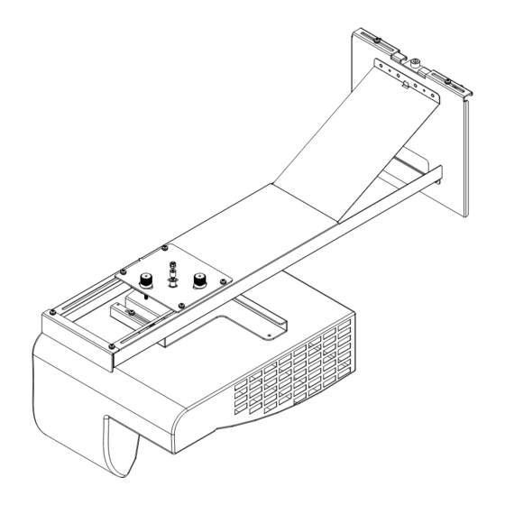
- Page 9 ASSEMBLY BREAKDOWN DIAGRAM Quick Installation Steps: Step 1: frame #1 setting drilling paper of ultra short series (1:1) to the proper position in up screen (see details please refer to P.9). Perforate the setting wall. (percussion drill and drill 8.5, 60mm depth) ...
- Page 10 INSTALLING STEP 1 Installing steps of holder 1: 1: Ensure the projector image allies with the center line of the screen, and determine the corresponding vertical distance value (H1) according to the projector distance chart. 2: Use D79X setting perforating paper of ultra short throw series (1:1) to determine the corresponding vertical distance.(H2) = (H1)-27.2mm ...
-
Page 11: Before Installation
INSTALLING STEP 2 Installing steps of structure frame # 2: 1: Place structure frame # 2’s neck into structure frame # 1’s up and down adjusting screw inserts. 2: Screw “B” screw (M4*10mm) into structure frame # 1’s corresponding threaded hole slightly. (2 PCS of both left and right side). - Page 12 INSTALLING STEP 3 Installing steps of structure frame # 2: 1: Loosen “C” screw. (2-M4*10mm) 2: Decline the three axis fine-tuner by 5 degree to aim at the registration mast. As illustrated in the following picture 2, install the slide-way on structure frame # 2’s slide-way, and switch it to intermediate position.
- Page 13 INSTALLING STEP 4 Installing steps of projector: 1: Loosen screw “H” (4X-M4*10), and remove structure frame # 7. 2: Use “I” screw (3-M4*10mm) to connect structure frame # 7 and projector, and assemble them together. 3: Assemble the connected structure frame # 7 and projector on structure frame # 6. ...
- Page 14 ADJUSTING STEP 1 Instruction of left and right adjusting movement: 1: Loosen screw “C”(2-M4*10mm), slightly. 2: Push structure frame # 3 left or right directly to conduct adjustment. 3: Adjust screw “C” to the proper position (X axis direction), and lock it.
- Page 15 ADJUSTING STEP 2 Instruction of up and down rotation movement: 1: Tuner “E” does clockwise movements and its function is to adjust structure frame # 6 to drive projector into clockwise (X axis direction) rotation adjustment.(picture A) 2: Tuner “E” does anti-clockwise movements and its function is to adjust structure frame # 6 to drive projector into anti-clockwise (X axis direction) rotation adjustment.(picture B) ...
- Page 16 ADJUSTING STEP 3 Instruction of left and right rotation movement: 1: Screw “F” for and rotate axis nut slightly. 2: Take the rotation axis as the axis (Z axis), adjust the setting disc through horizontal left and right rotation so that structure frame # 7 can drive projector towards horizontal rotation.(Z axis direction).
- Page 17 ADJUSTING STEP 4 Instruction of keystone adjustment movement: 1: Tuner “G” does clockwise movements and it’s function is to move structure frame # 6 to drive projector towards a clockwise (Y axis direction) rotation adjustment.(picture D) 2: Tuner “G” does anti-clockwise movements and it’s function is to move structure frame # 6 drive projector towards an anti-clockwise (Y axis direction) rotation adjustment.(picture C) ...
- Page 18 ADJUSTING STEP 5 Instruction of image size adjustment movement: 1: Loosen screw “D” (4-M4*10mm) slightly. Move structure frame # 5 forward and backward to adjust its position in Y axis. 2: For the distance between screen and projector, please refer to the projector sheet.(P. 7) 3: When the image size is OK, please tighten screw “D”.
- Page 19 ADJUSTING STEP 6 Instruction of image up and down adjustment movement: 1: Loosen screw “B” (4-M4*10mm) slightly. In order to adjust the image’s up and down position, turn “M” (up and down adjustment rotation screw) to make sliding structure frame #2 up and down, so as to adjust the image position up and down (Z axis direction).
- Page 20 CIMIC building 18 F zip code 200120 Tel: 86-21-58360088 Fax: 86-21-58360099 http://www.vivitek.com.cn ○ Vivitek EMEA Zandsteen 15 2132MZ Hoofddorp The Netherlands Tel: +31 20 655 0960 Fax:+31 20 655 0999 E-mail: nfo@vivitek.eu Web : www.vivitek.eu D79X ultra short series installation instructions - 2nd Edition...
Need help?
Do you have a question about the WMB-D7X1/WM3 and is the answer not in the manual?
Questions and answers