Table of Contents
Advertisement
Quick Links
Advertisement
Table of Contents

Related Manuals for Reliable 7200SB


Summary of Contents for Reliable 7200SB
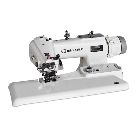
- Page 1 7200SB INDUSTRIAL BLINDSTITCH MACHINE INSTRUCTION MANUAL...
-
Page 2: Table Of Contents
< INSTRUCTION MANUAL> INDEX 1. Unpacking Machine ............1 2. Setting-up Machine ............I 3. Handwheel Rotation and Speed ........1 4. Oiling and Maintenance ...........1 5. Replacing Needle ............. 2 6. Threading Machine ............3 7. Inserting the Work and Starting to sew ......4 8. -
Page 3: Unpacking Machine
1. Unpacking Machine Open packing box by carefully removing its cover so as not to damage the machine or those of its parts which project from the top, such as the tension parts. Small accessory parts are packed separately in individual packages. Do not discard any packing materials without prior scrutiny as to contents. -
Page 4: Replacing Needle
Do not operate without material under the presser foot unless the knee lever is depressed. This will prevent damage to the needle and the feed dog as well as the feed plattens. 5. Replacing Needle Turn handwheel away from operator (clockwise) until needle reaches the end of its return stroke ( extreme left hand position). -
Page 5: Threading Machine
Always replace bent or blunt needles. They affect the satisfactory operation of the machine. (see Fig. l) See par. l O concerning needle sysetm to be used in B lindstitch Machines. 6. Threading Machine Turn handwheel of machine in clockwise direction away from operator until needle carrier reaches its furthest lefthand position. -
Page 6: Inserting The Work And Starting To Sew
7. Inserting the Work and Starting to Sew Depress knee lifter. This causes the feed plate to swing downward and creates a gap between the presser foot and the feed plate. Insert the work in the gap just opened in such a manner that the folded or sewn edge of the material is alongside the edge guide of the presser foot. -
Page 7: Stitch Length Regulation
9. Stitch Length Regulation Stitch length adjustment can be easily effected by adjusting needle driving eccentric in arm. Go about it as follows : Tum handwheel by hand pushing plunger until same is felt to drop into a recess within the mechanism inside the arm of the machine. With the plunger remaining depressed into this recess continue turning the handwheel either forward or in reverse until the desired number of stitches per inch is visible on indivator. -
Page 8: Skip Stitch Device
11. Skip Stitch Device The position of grip at the right side of the machine controls the skip stitch device. ( see Fig. 5) When this grip points towards NO SKIP. the needle catches the material at each stitch. Pointing towards SKIP. the needle penetrates the material at every other stitch. -
Page 9: Stitch Stabilizing Guide (For H-1012)
14. Stitch Stabilizing Guide (for H-10I2) Stitch Stabilizing Guide is effective for soft and uniform stitch on extremely thin material. If required tight stitch on thin and medium materials, loosen Stitch Stabilizing Guide Set Screw to take off Stitch Stabilizing Guide. Be sure to tighten Stitch Stabilizing Guide Set Screw firmly on presser foot of same position after took off the Stitch Stabilizing Guide. -
Page 10: Safety Instructions
SAFETY INSTRUCTIONS: 1.1. Instruction and trial-run must be done by professional technician; 1.2. Please ensure the grounded wire is working well; 1.3. Do not step on the foot pedal when motor turns on; 1.4. Control box and motor cover are forbidden to be opened when power turn-on;... -
Page 11: Technician Model Parameter Diagram
TECHNICIAN MODEL PARAMETER DIAGRAM: Parameter Factory Description Adjusting Scope Remark Code Setting 0: Reverse turn Direction of rotation P-02 1: Clockwise turn The needle Angle P-03 6-18 Sewing-begin speed 200-800rpm P-04 300-1200 Speed-up and slow-down P-05 0-999needle Setting the seam P-06 Reserve P-07... -
Page 12: Fault Solution Guide
FAULT SOLUTION Error Reason Content Code The gap between handle wheel and motor cover is too big; Er01 No found needle position Nine plug does not connect well; Motor hall broken, it should change new motor; The magnet in handle wheel is lost. Speed regulator plug not plug-in or The speed regulator is badly connected;... - Page 16 Machine Frame & Covers Components Ref. No. Parts No. Description 4139 Arm Side Cover 4144 Arm Side Cover Set Screw 4137 Arm Side Cover Plate 5227 Arm Side Cover Plate Screw 4138-B Arm Top Cover Plate 4141 Arm Top Cover Plate Screw Arm Top Cover Plate Washer 4140-A AMl00-B Machine Frame...
- Page 17 Direct Drive Motor & C omponents M14-24 101SD-1 LD00271 LD00003 LD00237 LD00003...
- Page 19 Main Shaft Mechanism Components Ref. No. Parts No. Description Main Shaft Bushing (Front) 11005 Main Shaft Bushing Set Screw 4217 Oiling Felt 4128-A Oil Cap 4133 Counterweight (w/Stitch Length Numbers) Counterweight Set Screw (Short) Counterweight Set Screw (Long) 4134 Stitch Length Indicator Stitch Length Indicator Set Screw 11006 Main Shaft Bushing (Rear)
- Page 31 Work Plate, Knee Press & Belt Cover Parts Components Ref. No. Parts No. Description 4153 Work Plate 4156 Work Plate Latch 5230 Work Plate Latch Set Screw 4157-A Work Plate Bracket 4159 Work Plate Bracket Spring Pin 4160 Work Plate Bracket Leaf Spring (Long) 4161 Work Plate Bracket Leaf Spring (Short) 4048-A Work Plate Bracket Leaf Spring Set Screw...
- Page 38 What do I do when the fabric is gathering? Adjust the thread tension gradually counter clockwise to loosen the tension. There are 2 common types of blindstitch needles: LW X 5T & LW x 6T 7200SB/DB use LW X 6T...
- Page 39 7200SB, 7200DB, WITH POSITIONI NG MOTOR USER’S BULLETIN TIME USERS OF BLINDSTITCH MACHINES – PLEASE READ CAREFULLY If you have never used a blindstitch machine before, it is very important that you read these instructions carefully. Failure to read may limit or void the manufacturer’s warranty.
- Page 40 NEEDLE UP NEEDLE DOWN POSITION EXTREME POSITION LEFT EXTREME RIGHT The machine is driven with a needle positioning motor. On stop command the needle will always stop in the down position - (extreme right) To remove the work piece at the end of a seam – heel back on the foot treadle and the needle will automatically position up –...
- Page 41 SIZE LW X 6T MATERIAL 2 1/2 Cotton, Silk, Dacron and Similar type light weight materials 3 1/2 Medium Weight materials. Woolen and others Thick material for drapery and others 4 1/2...
- Page 42 If Reliable is unable to repair or replace a Reliable Product, it will refund the current value of that Reliable Product at the time the warranty claim is made.
- Page 44 1 800 268 1649 www.reliablecorporation.com...
Need help?
Do you have a question about the 7200SB and is the answer not in the manual?
Questions and answers