Table of Contents
Advertisement
Quick Links
Advertisement
Table of Contents

Related Manuals for Reliable 4400SW


Summary of Contents for Reliable 4400SW
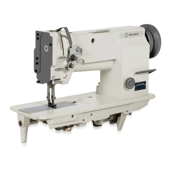
- Page 1 4400SW/4400TW INDUSTRIAL SEWING MACHINE INSTRUCTION MANUAL...
-
Page 2: Table Of Contents
CONTENTS Operation instructions 1. Brief introduction 2. Main specifications 3. Installation and preparation 3.1 Installation 3.1.1 Location of the machine 3.1.2 Installing oil reservoir 3.1.3 Mounting machine head 3.1.4 Mounting knee lifter 3.1.5 Installing the motor 3.1.6 Connecting the clutch lever to the pedal 3.1.7 Installing the thread winder 3.1.8 Installing the thread spool stand 3.2 Preparation... - Page 3 3. Upper shaft and presser foot parts 19 22 4. 4400TW Needle bar motion and Lower feed parts 23 26 4400SW Needle bar motion and Lower feed parts 27 30 4400TW Rock shaft and thread looping parts 31 34 4400SW Rock shaft and thread looping parts 35 38 8.
-
Page 4: Brief Introduction
The difference between the two models: 4400TW adopts twin-needle, two large horizontal hooks with auto lubrication. With the parts it can form ten different needle gauges. 4400SW adopts single needle and form single line double lockstitch form. 2. Main Technical Specification 1 Application:... -
Page 5: Mounting Knee Lifter
3.1.4 Knee control presser foot lifter installation(Fig.3) a. Installing Install Connector A , Bell Crank B , Bell C in the order shown in Fig.3. b. Adjustment (Fig.4) In the order of the following: 1.When the presser foot at its lowest posi- tion, keep the crank in the position shown by b in the figure, turn Knee Control Stop Adjusting... -
Page 6: Connecting The Clutch Lever To The Pedal
3.1.6 Connecting the clutch lever to the pedal (Fig.6) 1)The optimum tilt angle of pedal A with floor is approx.30 degree. 2)Adjust the clutch of the motor so that clutch lever C and draw bar B run in line. 3)The machine balance wheel should rotate coun- terclockwise for normal sewing when view from opposite side of balance wheel G . -
Page 7: Examination
3.2.2 Examination Though every machine is confirmed by strict inspec- tion and test before delivery, the machine parts may be loosed or deformed after long. distance transportation with jolt. A thorough examination must be performed after cleaning the machine . Turn the balance wheel to oil mark see if there is running obstruction, parts collision, uneven resistance or abnormal nosie. -
Page 8: Operation
4. Operation 4.1 Coordination between needle, thread and sewing material Please use needle DP 17,Nm125-180.The coarseness of needle should be in accordance with the nature of material. If stitch on heavy duty material with a slim needle, the needle will be easily bent, skip or thread clearance breakage occurs, on the contrary, stitch on tightly woven material with a very coarse needle, the material will... -
Page 9: Winding Adjustment
4.3.2 Winding adjustment (Fig.15) 1) Wound bobbin thread should be neat and tight, if not , adjust the thread tension by turning tension stud thumb nut A of bobbin winder tension bracket. Note: nylon or polyester thread should be wound with light tension , otherwise bobbin D might be... -
Page 10: Setting The Bobbin
4.3.5 Placing bobbin (Fig.18) Note: when bobbin is placed into the bobbin case, thread the thread should be wound properly in the correct direction shown in the figure. 4.3.6 Drawing thread from the bobbin (Fig.19) sliding plate a. Draw the thread end to Bobbin Slot (1) shown in the figure, and pull it out down through the inner bobbin stop piece. -
Page 11: Adjusting The Pressure Of Presser Foot
b. If the needle thread is too loose and the bobbin thread is too tight, then shows as Fig. 20C, And turn the thread tension screw clockwise to increase the needle thread tension; or turn loose the bobbin lace screw to reduce the bobbin thread needle thread tension tension. -
Page 12: Regulating The Strength On The Safety Clutch Device
b. When the stop plate stops the balance wheel, more strength is needed to turn the balance wheel to reset the safety clutch device. C. Release the button in the bed. So the resetting of it is OK. (See Fig.26) stop plate 5.3.3 Regulating the strength on the safety clutch device(Fig.27) -
Page 13: Presser Foot Lift Volume Adjustment
5.5 Presser foot lift volume adjustment (Fig.29) when stitch on the very elastic material or the thickness of the sewing material is changed. The ad- justment should be done in the following order: crank 1. Loosen the special screw. special screw 2. -
Page 14: Parts Manual
Parts Manual... -
Page 15: 00Tw Arm Parts
1. 4400TW Arm Parts 42 41 22 21 20 19 45 46 46 47 47 48 61 60 58 57 -11-... - Page 16 1. 4400TW Arm Parts Item Part number Description P cs 1WF1-001 1WF1-002 Screw Screw 1WF1-041 Trade mark plate 1WF1-042 Model plate Nail 1WF1-015 Upper thread guide 1WF1-016 Screw 1WF1-017 Back cover 1WF1-011 Screw Washer 1WF1-032 Cover 1WF1-038 Front slide plate 1WF1-039 Screw 1WF1-019...
- Page 17 1. 4400TW Arm Parts 42 41 22 21 20 19 45 46 46 47 47 48 61 60 58 57 -13-...
- Page 18 1. 4400TW Arm Parts Item Part number Description P cs 1WF1-012 Guid set plate 1WF1-021 Set plate 1WF1-020 Oil retainer 1WF1-035 Tread releasing lever 1WF1-037 Pin shaft 1WF1-023 Thread releasing lever 1WF1-033 Right sliding plate 1WF1-040 Left sliding plate 1WF1-029 Plug 1WF1-022 Plug...
-
Page 19: 00Sw Arm Parts
2. 4400SW Arm Parts 40 39 20 21 43 44 45 46 51 50 56 55 -15-... - Page 20 2. 4400SW Arm Parts Item Part number Description P cs 9WF1-007 1WF1-002 Screw Screw 9WF1-005 Trade mark plate 9WF1-006 Modle plate Nail 1WF1-015 Upper thread guide 1WF1-016 Screw 1WF1-017 Back cover 1WF1-011 Screw Washer 1WF1-032 Ccover 1WF1-038 Front slide plate...
- Page 21 2. 4400SW Arm Parts 40 39 20 21 43 44 45 46 51 50 56 55 -17-...
- Page 22 2. 4400SW Arm Parts Item Part number Description P cs 1WF1-020 Oil retainer 9WF1-004A Throat plate 1WF1-043 Spring retaining plate 1WF1-023 Thread releasing lever 1WF1-033 Right sliding plate 1WF1-040 Left sliding plate 1WF1-029 Plug 14.5 1WF1-022 Plug 12.7 1WF1-031 Back fitting cover...
- Page 23 3. Upper Shaft Presser Foot Parts 43 39 40 34 35 37 38 8 13 14 3 36 -19-...
- Page 24 3. Upper Shaft Presser Foot Parts Item Part number Description P cs 1WF2-025 Upper shaft 1WF2-022 Front bushing 1WF2-023 Screw 1WF2-024 Oil felt 1WF2-021 Needle crank 1WF2-020 Screw 1WF2-007 Screw 1WF2-010 Screw 1WF2-009 Screw 1WF5-026 Presser foot lift eccentric cam Stop ring 1WF5-041 Slot for front crank sliding block...
-
Page 25: Upper Shaft And Presser Foot Parts
3. Upper Shaft Presser Foot Parts 43 39 40 34 35 37 38 8 13 14 3 36 -21-... - Page 26 3. Upper Shaft Presser Foot Parts Item Part number Description P cs Screw 1WF2-038 1WF5-001 Connecting lever 1WF5-025 Connecting screw 1WF5-044 Washer Oil tube assembly 1WF5-023 Sping 1WF5-024 Presser foot lift rear crank 1WF5-045 Screw 1WF4-018 Presser foot lift front crank 1WF5-038 Screw 1WF5-028...
-
Page 27: 00Tw Needle Bar Motion And Lower Feed Parts
4. 4400TW Needle Bar And Lower Feed Parts 7 8 9 12 13 38 40 43 42 44 43 45 46 47 48 49 1 72 71 70 74 73 77 76 75 59 61 60 59 63 62 58 45 57 56 55 54 67 66 64 65 63 54 57 56 -23-... - Page 28 4. 4400TW Needle Bar And Lower Feed Parts Item Part number Description P cs 1WF5-017 Oil wick 1WF5-018 Shaft for needle bar motion holder 1WF5-031 Screw 1WF5-019 Screw 1WF2-018 Oil wick 1WF2-017 Bushing for thread take-up lever hole 1WF2-016 Thread take-up lever 1WF2-011 Sliding block 1WF2-019...
- Page 29 4. 4400TW Needle Bar And Lower Feed Parts 7 8 9 12 13 38 40 43 42 44 43 45 46 47 48 49 1 72 71 70 74 73 77 76 75 59 61 60 59 63 62 58 45 57 56 55 54 67 66 64 65 63 54 57 56 -25-...
- Page 30 4. 4400TW Needle Bar And Lower Feed Parts Item Part number Description P cs Bushing for needle bar motion shaft 1WF5-027 Set screw 1WF5-028 Shaft for needle bar motion 1WF5-048 Screw 1WF4-018 Rear crank for needle bar motion 1WF5-005 Connecting nut 1WF5-004 Link for needle bar notion 1WF5-003...
- Page 31 5. 4400SW Needle Bar And Lower Feed Parts 7 8 9 12 13 38 40 43 42 44 43 45 46 47 48 49 1 72 71 70 74 73 77 76 75 59 61 60 59 63 62 58 45 57 56 55 54...
- Page 32 5. 4400SW Needle Bar And Lower Feed Parts Item Part number Description P cs 1WF5-017 Oil wick 1WF5-018 Shaft for needle bar motion holder 1WF5-031 Screw 1WF5-019 Screw 1WF2-018 Oil wick 1WF2-017 Bushing for thread take-up lever hole 1WF2-016 Thread take-up lever...
-
Page 33: 00Sw Needle Bar Motion And Lower Feed Parts 27
5. 4400SW Needle Bar And Lower Feed Parts 7 8 9 12 13 38 40 43 42 44 43 45 46 47 48 49 1 72 71 70 74 73 77 76 75 59 61 60 59 63 62 58 45 57 56 55 54... - Page 34 5. 4400SW Needle Bar And Lower Feed Parts Item Part number Description P cs 1WF5-027 Bushing for needle bar motion shaft 1WF5-028 Set screw 1WF5-048 Shaft for needle bar motion 1WF4-018 Screw 1WF5-005 Rear crank for needle bar motion 1WF5-004...
- Page 35 6. 4400TW Rock Shaft And Thread Looping Parts 31 32 34 35 39 40 41 42 43 50 51 52 47 48 53 54 £- 31£-...
- Page 36 6. 4400TW Rock Shaft And Thread Looping Parts Item Part number Description P cs 1WF2-063 Right hook saddle 1WF2-060 Screw 1WF2-059 Upper bushing of hook saddle 1WF2-061 Lower bushing of hook saddle 1WF2-064 Hook assembly 1WF2-065 Bobbin 1WF2-070 Oil wick 1WF2--069 Hinge shaft 1WF2-072...
-
Page 37: 00Tw Rock Shaft And Thread Looping Parts 31
6. 4400TW Rock Shaft And Thread Looping Parts 31 32 34 35 39 40 41 42 43 50 51 52 47 48 53 54 £- 33£-... - Page 38 6. 4400TW Rock Shaft And Thread Looping Parts Item Part number Description P cs 1WF2-036 Oil wick 1WF2-056 Rock shaft 1WF2-006 Feed dog lift cam 1WF2-019 Set screw 1WF2-057 Right bushing for rock shaft 1WF2-058 Oil wick Split stop ring 1WF4-041 Spring 1WF4-042...
- Page 39 7. 4400SW Rock Shaft And Thread Looping Parts 30 31 33 34 38 39 40 41 42 49 50 51 46 47 52 53 -35-...
- Page 40 7. 4400SW Rock Shaft And Thread Looping Parts Item Part number Description P cs 1WF2-063 Right hook saddle 1WF2-060 Screw 1WF2-059 Upper bushing of hook saddle 1WF2-061 Lower bushing of hook saddle 1WF2-064 Hook assembly 1WF2-065 Bobbin 1WF2-070 Oil wick...
-
Page 41: 00Sw Rock Shaft And Thread Looping Parts 35
7. 4400SW Rock Shaft And Thread Looping Parts 30 31 33 34 38 39 40 41 42 49 50 51 46 47 52 53 -37-... - Page 42 7. 4400SW Rock Shaft And Thread Looping Parts Item Part number Description P cs 1WF2-056 Rock shaft 1WF2-006 Feed dog lift cam 1WF2-019 Set screw 1WF2-057 Right bushing for rock shaft 1WF2-058 Oil wick Split stop ring 1WF2-041 Spring 1WF4-0421WF4-042...
-
Page 43: Stitch Length Adjusting Parts 39
8.Stitch Length Adjusting Parts 16 15 30 29 28 26 -39-... - Page 44 8.Stitch Length Adjusting Parts Item Part number Description P cs 1WF4-025 Stitch length adjusting swing lever 1WF4-030 Screw 1WF4-026 Set screw 1WF4-014 Stitch length link 1WF4-028 Stitch length link eccentric shaft 1WF4-046 Reverse sewing shaft 1WF4-047 Reverse sewing crank 1WF4-027 Tension screw 1WF4-021 Set screw...
- Page 45 9.Presser Foot Lift Parts -41-...
- Page 46 9.Presser Foot Lift Parts Item Part number Description P cs 1WF5-040 Sliding block rail 1WF5-039 Screw 1WF3-011 Screw 1WF3-010 1WF3-013 Screw 1WF3-014 Spring 1WF3-012 Knee lift lever 1WF3-015 Pressure adjusting screw 1WF3-016 Pressure bar spring lever 1WF3-018 Screw 1WF3-017 Screw 1WF3-019 Knee control crank assembly 1WF3-021...
-
Page 47: Knee Lifter Parts 41
9.Presser Foot Lift Parts -43-... - Page 48 9.Presser Foot Lift Parts Item Part number Description P cs 22T9-001A2 Screw 22T9-001A3 Washer Retain ring 1WF3-028 Knee lifter stop bracket 22T9-001A9 Adjust screw 22T9-001A10 Adjust nut 22T9-007C2 Screw 22T9-001A7 Position spring 1WF3-027 Hinge pin 22T9-003B4 Screw 22T9-003B3 Connector 22T9-003B2 Bent rod 22T9-003B7 Screw...
- Page 49 10. 4400TW Lubrication Parts 48 21 47 16 46 49 20 23 45 16 30 29 35 34 16 36 23 38 23 -45-...
- Page 50 10. 4400TW Lubrication Parts Item Part number Description P cs 1WF6-001 Oil felt press spring 1WF6-034 Screw 1WF6-003 Oil felt 1WF6-005A Oil pipe 1WF6-004 Oil wick 1WF6-007 Oil cup 1WF6-008 Oil cup cover Screw 1WF6-009 Spring pin 1WF6-006 Wick press spring 1WF6-010 Oil pipe 1WF6-011...
-
Page 51: 00Tw Lubrication Parts 45
10. 4400TW Lubrication Parts 48 21 47 16 46 49 20 23 45 16 30 29 35 34 16 36 23 38 23 -47-... - Page 52 10. 4400TW Lubrication Parts Item Part number Description P cs 1WF6-019 Washer 1WF6-020 Filter screw 1WF6-017 Oil filter bracket 1WF6-028 Oil pipe clamp 1WF6-035 Oil pipe 1WF6-036 Oil pipe clamp 1WF6-038 Oil tray assembly 1WF6-041 Oil wick 1WF6-040 Oil pipe 1WF6-039 Oil pipe 1WF6-034...
- Page 53 11. 4400SW Lubrication Parts 13 14 11 12 8 10 38 23 37 36 -49-...
- Page 54 11. 4400SW Lubrication Parts Item Part number Description P cs 1WF6-001 Oil felt press spring 1WF6-034 Screw 1WF6-003 Oil felt 1WF6-005A Oil pipe 1WF6-004 Oil wick 1WF6-007 Oil cup 1WF6-008 Oil cup cover Screw 1WF6-009 Spring pin 1WF6-006 Wick press spring...
-
Page 55: 00Sw Lubrication Parts 49
11. 4400SW Lubrication Parts 13 14 11 12 8 10 38 23 37 36 -51-... - Page 56 11. 4400SW Lubrication Parts Item Part number Description P cs 1WF6-019 Washer 1WF6-020 Filter screen 1WF6-017 Oil filter bracket 1WF6-028 Oil pipe clamp 1WF6-035 Oil pipe 1WF6-036 Pipe clamp 1WF6-038 Oil tray assembly 1WF6-041 Oil wick 1WF6-040 Oil pipe 1WF6-034...
-
Page 57: Accessories 53
12.Accessories 18 18 -53-... - Page 58 12.Accessories Item Part number Description P cs 33TF-010 Accessories bag 22T9-007F1 Hinge pin 22T9-007F2 Hinge pin socket 22T9-009 Cushion 22T9-010 Cushion 1WF2-065 Bobbin 33TF-011 Oil pot 33TF-016 V-belt 1F-009 Needle 1F-011 Hex key 1F-010 Hex key 33TF-012 Screwdriver 33TF-013 Screwdriver 33TF-014 Screwdriver 58T0-007C...
- Page 60 1 800 268 1649 www.reliablecorporation.com...
Need help?
Do you have a question about the 4400SW and is the answer not in the manual?
Questions and answers