Table of Contents

Related Manuals for Primex SP6R


Summary of Contents for Primex SP6R
- Page 1 SP6R CONTROLLER User Manual DIGITAL DISPLAY WITH BARGRAPH 6 RELAY OUTPUTS OUTPUT STATUS LED 4-20mA INPUT Ashland, OH 800-363-5842 Clearwater, FL 800-349-1905 Detroit Lakes, MN 888-342-5753 Milford, OH 513-831-9959 WWW.PRIMEXCONTROLS.COM...
-
Page 2: Table Of Contents
Electrical Connections ........................ 8 Function Keys / Displays ......................9 Setting Up Levels and Simulation ..................10-11 Configuration ........................12-13 Configuration Mode Parameters ....................14 Run Mode Parameters ......................15 Notes ............................16 WWW.PRIMEXCONTROLS.COM PRIMEX™ SP6R Level Controller User Manual... -
Page 3: Specifications
Front Panel: IEC Standard IP54 (with additional gasket) for indoor use. Rear Case: IEC Standard IP20. BAR GRAPH 20 segment bar graph display for process value. Each bar represents 5% of full scale. PRIMEX ™ SP6R Level Controller User Manual... -
Page 4: Introduction
• a three pin power supply connector block (P1) • a five pin transducer connector block (P2) • a 18 pin relay output connector block (P3) The SP6R-N4X version includes a controller mounted within a NEMA 4X enclosure with a pre-wired power supply and terminal blocks. PRIMEX ™... -
Page 5: Warnings
Leave a minimum of 10 mm space for ventilation between the top and bottom edges of the controller and enclosure walls. EXPLOSION OR FIRE HAZARD Do not use this product with flammable liquids. Do not install in hazardous locations as defined by National Electrical Code, ANSI/NFPA 70. PRIMEX™ SP6R Level Controller User Manual... -
Page 6: Installation & Dimension Data
INSTALLATION & DIMENSIONAL DATA FIGURE 1 Dimensions and panel cut-out. Dimensions are indicative and may be subject to change without notification. PRIMEX™ SP6R Level Controller User Manual... - Page 7 PRIMEX ™ SP6R Level Controller User Manual...
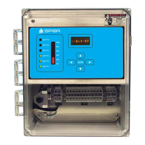
- Page 8 INSTALLATION & DIMENSIONAL DATA FIGURE 2 Standard SP6R level controller kit. PRIMEX ™ SP6R Level Controller User Manual...
-
Page 9: Electrical Connections
NOTE: To avoid ground loops, the shield of the signal cable must only be grounded at one end. 3. OUTPUT RELAY CONNECTIONS The relay outputs are rated up to 10 A (resistive) at 240 VAC, fuse protection is required individually or as a group. PRIMEX ™ SP6R Level Controller User Manual... -
Page 10: Function Keys / Displays
Pressing once will increment the current value by one unit. Pressing and holding will begin repeatedly incrementing after a short delay. If the opera- tor continues to hold the key, the value continues to increment at a faster rate. PRIMEX ™ SP6R Level Controller User Manual... -
Page 11: Setting Up Levels And Simulation
SETTING UP LEVELS AND SIMULATION LEVEL DISPLAY FLASHING SELECT STORE EDIT FIGURE 4 Example of how to move from the level display screen through each set-point and to change set-point 2. Continued on next page... PRIMEX ™ SP6R Level Controller User Manual... - Page 12 For an emptying application, the ON set-point must be greater than the OFF set-point. For a fill- ing application, the ON set-point must be less than the OFF set-point (Refer to FIGUIRE 5). NOTE: For proper operation of the SP6R controller, the ON and OFF set-points must not be set to the same value.
-
Page 13: Configuration
(out of the wet well) should be zero. If it is not, add or subtract (negative) a value to bring the display to zero. Check the level readout to verify it is zero. If not, try changing the offset again. PRIMEX ™ SP6R Level Controller User Manual... - Page 14 Begin with UNITS, 4 mA, 20 mA, BAR MIN, BAR MAX, OFFSET, and back to UNITS. NOTE: Eight (8) seconds of inactivity (no keys pressed) will terminate the configuration menu and exit back to the run menu. PRIMEX ™ SP6R Level Controller User Manual...
-
Page 15: Configuration Mode Parameters
CONFIGURATION MODE PARAMETERS DEFAULT USER OOOUNITS FT, IN, CM, %, F, PS, BR, (NONE) OOOO4OMA 999.9 0.0 FT OOO20OMA 999.9 10.0 FT OBAROMIN 999.9 0.0 FT OBAROMAX 999.9 10.0 FT OOOFFSET -9.9 0.0 FT NOTES PRIMEX™ SP6R Level Controller User Manual... -
Page 16: Run Mode Parameters
6.5 FT OSP4OOFF 999.9 6.0 FT OOSP5OON 999.9 8.5 FT OSP5OOFF 999.9 8.0 FT OOSP6OON 999.9 9.5 FT OSP6OOFF 999.9 9.0 FT 4 mA value in 20 mA value in SIMULATE configuration configuration PRIMEX ™ SP6R Level Controller User Manual... -
Page 17: Notes
NOTES PRIMEX ™ SP6R Level Controller User Manual... - Page 18 ASSEMBLED IN THE Ashland, OH 800-363-5842 Clearwater, FL 800-349-1905 Detroit Lakes, MN 888-342-5753 Milford, OH 513-831-9959 WWW.PRIMEXCONTROLS.COM PN 1038547A REV 09/13 © 2013 SJE-Rhombus® PRIMEX ™ is a trademark of SJE-Rhombus®...
Need help?
Do you have a question about the SP6R and is the answer not in the manual?
Questions and answers