
Related Manuals for Primex LEVEL VIEW


Summary of Contents for Primex LEVEL VIEW
- Page 1 LEVEL VIEW PUMP STATION CONTROLLER Ashland, OH 800-363-5842 Clearwater, FL 800-349-1905 Detroit Lakes, MN 888-342-5753 844-4PRIMEX (477-4639) Milford, OH 513-831-9959 WWW.PRIMEXCONTROLS.COM...
-
Page 2: Table Of Contents
Pump Amps Setup .............. 10 VFD Setup ................11 Level Setup ................. 12 Flow Setup ................14 ™ Level View Power up Screen ..........15 I/O Terminal Configuration ..........15 I/O Table ................16 Electrical Wiring Diagrams ..........17 Dimensions and Mounting ..........19 DIP Switch Settings &... - Page 3 Do not connect power to this equipment if it has been damaged or has any missing parts. • The Level View™ contains no serviceable parts; do not attempt to repair this equipment. • Do not install in areas with: excessive or conductive dust, corrosive or flammable gas, moisture or rain, excessive head, regular impact shocks, or excessive vibration.
-
Page 4: Introduction And Specifications
INTRODUCTION & SPECIFICATIONS Congratulations, and thank you for your purchase of the Level View ™ controller. This manual explains ™ the features and operations of the Level View controller which was designed specifically for pump stations. It can be configured for pump up or pump down applications. It uses a level transducer with two (2) back up float switches. -
Page 5: Main Screen
The Main screen gives the operator an overview of the lift station status. Message Bar Backup Float Status Pump Status Pump Cycles Hour Meter Pump Flow Setpoint Status Pump Amps Call Sequence Low Battery Communication Alarm Present Indicator Active ACCESSING THE MENU SCREEN PRIMEX ® Level View ™ Controller User Manual... -
Page 6: Datalog
DATA LOG The Level View ™ controller will log daily station data for 7 days including today’s data since midnight. Pump 1, Pump 2, & Pump 3 cycles/day, runtime/day, gallons/day are recorded. Day 1 through Day 7 can be accessed by using the navigation buttons. -
Page 7: Active Alarms
Time On indicates the time the alarm occurred. If you touch the magnifying glass, the details of any active alarm will be displayed. To return to the Pending Alarm screen, press the ESC button. PRIMEX ® Level View ™ Controller User Manual... -
Page 8: Alarm History
19 PANEL INTRUSION The control panel door has been opened 20 LOW BATTERY The controller battery is low Change battery with power on controller. Power cycle controller to reset screen indicator. PRIMEX ® Level View ™ Controller User Manual... -
Page 9: Setup
SETUP PRIMEX ® Level View ™ Controller User Manual... -
Page 10: Sensor Setup
Empty (Pump Down application) or Fill (Pump Up application) Lead Select P1, P2, P3 (if 3 pumps selected), or Auto Access Password 0= No password, 1-9999 password set Press the yellow button for each mode to cycle through options. PRIMEX ® Level View ™ Controller User Manual... - Page 11 Pressing the button opens the INPUT/OUTPUT STATUS screen. This screen enables the user to monitor the status of all Inputs and Outputs of the controller. This is a very useful tool when troubleshooting. PRIMEX ® Level View ™ Controller User Manual...
-
Page 12: Pump Data Screen
17. General Alarm PUMP DATA SCREEN The Pump Data screen is for information only. It is a record of the pump HP, Volts, and FLA. This data can be viewed remotely when connected to the PRIMEX ® PUMP WATCH ®... -
Page 13: Pump Amps Setup
PUMP AMPS SETUP The Level View ™ controller uses a current transducer for each pump. The measuring range of the current transmitter is typically listed on the transducer. The default unit has a 0-100A range. Current Transducers To configure the controller to match the current transducer, touch the Pump X Amp Range button. -
Page 14: Vfd Setup
VFD SETUP ™ The Level View controller is capable of pump speed control based on level. Hold Time at 60Hz on Ramp Up (sec): When the pump starts, it will automatically ramp up to full speed (60Hz) for the number of seconds set in this parameter. When the timer times out, the VFD will follow the speed curve set by the other parameters. -
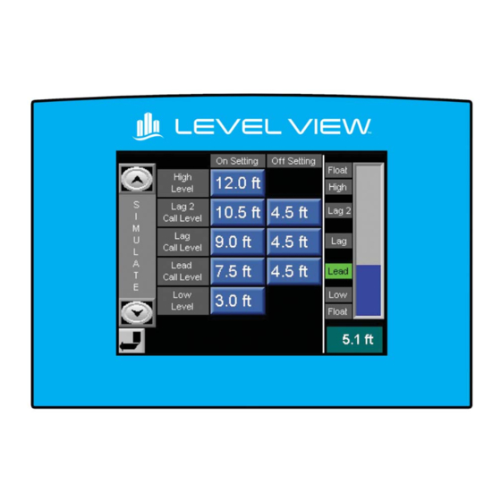
Page 15: Level Setup
These set-points are only accessible in TRIPLEX pump operation mode. High Level When the level rises above this level, then a high alarm will be set. The High condition will reset 10 seconds after the level falls below this set-point. PRIMEX ® Level View ™ Controller User Manual... - Page 16 Setup screen. Back up float switch operation: Two back up floats are strongly recommended. They need to be wired to control the pumps independently of the Level View ™ controller. The float inputs into the Level View ™...
-
Page 17: Flow Setup
Rectangular button. If the tank is cylindrical, enter the tank diameter using the (d) tank diameter display. If the tank is rectangular, enter the tank dimensions using the (a) and (b) display buttons. PRIMEX ® Level View ™ Controller User Manual... -
Page 18: Level View ™ Power Up Screen
™ LEVEL VIEW POWER UP SCREEN (VERSION) On power up, the screen will display the version of the program. Always have the version number ready when contacting the factory for service. I/O TERMINAL CONFIGURATION PRIMEX ® Level View ™ Controller User Manual... -
Page 19: I/O Table
LEVEL VIEW I/O TABLE ™ DIGITAL OUTPUT TERMINALS DIGITAL INPUT TERMINALS INPUT TYPE DESCRIPTION INPUT TYPE DESCRIPTION COM NA NO CONNECTION INPUT COMMON (0~8) O0 NA NO CONNECTION I0 DIGITAL PNP PUMP 1 RUNNING O1 NA NO CONNECTION I1 DIGITAL PNP... -
Page 20: Electrical Wiring Diagrams
ELECTRICAL WIRING DIAGRAM CR13 CR14 CR15 CR16 CR17 CR18 CR19 CR20 CR21 CR22 CR23 CR24 CR25 CR26 DIGITAL INPUTS DIGITAL OUTPUTS PRIMEX ® Level View ™ Controller User Manual... - Page 21 SHLD SHLD PUMP 2 SPEED SHLD SHLD COMMAND (4-20mA) SHLD SHLD PUMP 3 SPEED SHLD SHLD COMMAND (4-20mA) SHLD SHLD ADJUSTED LEVEL SHLD SHLD RE-TRANSMIT (4-20mA) SHLD SHLD ANALOG INPUTS ANALOG OUTPUTS PRIMEX ® Level View ™ Controller User Manual...
-
Page 22: Dimensions And Mounting
DIMENSIONS AND MOUNTING 7.75” 2.76” 2.47” 0.29” 2.78” PRIMEX ® Level View ™ Controller User Manual... -
Page 23: Dip Switch Settings & I/O Module Jumper
Analog Input jumper settings - Bottom of PCB Board Set to 4-20mA Input JUMPER FUNCTION POSITION ™ DEFAULT (UNI) LEVEL VIEW ANALOG INPUT 0 ANALOG INPUT 1 ANALOG INPUT 2 ANALOG INPUT 3 Analog Output jumper settings - Top of PCB Board Set to 4-20mA Output... -
Page 24: Controller Setpoints List
LEVEL VIEW CONTROLLER SETPOINTS LIST ™ STATION NAME: START UP DATE: CONTROLLER REV: SENSOR SETUP FACTORY USER SETTING Level Transducer Range 99.9 Level Transducer Offset 99.9 VFD CONTROL SETUP Frequency at Lag 2 Level 60.0 Start Frequency at Lag Level 60.0... - Page 25 Ashland, OH 800-363-5842 Clearwater, FL 800-349-1905 Detroit Lakes, MN 888-342-5753 844-4PRIMEX (477-4639) Milford, OH 513-831-9959 WWW.PRIMEXCONTROLS.COM PN 1043154A © 2013 SJE-Rhombus® Rev 11/14 PRIMEX is a trademark of SJE-Rhombus®...
Need help?
Do you have a question about the LEVEL VIEW and is the answer not in the manual?
Questions and answers