
Related Manuals for Primex STATION VIEW


Summary of Contents for Primex STATION VIEW
- Page 1 STATION VIEW DUPLEX PUMP CONTROLLER User Manual +1-844-4PRIMEX (477-4639) WWW.PRIMEXCONTROLS.COM...
-
Page 2: Table Of Contents
Flow (continued) & Amps ............ 14 Dry Run & High Amp ............15 Date/Time, Max Run Time, Password & Pump Data ..16 I/O Status ................17 I/O Configuration, Dimensions & Mounting ......18 PRIMEX Station View Controller User Manual ™ ®... - Page 3 Do not connect power to this equipment if it has been damaged or has any missing parts. • The Station View™ contains no serviceable parts; do not attempt to repair this equipment. • Do not install in areas with: excessive or conductive dust, corrosive or flammable gas, moisture or rain, excessive head, regular impact shocks, or excessive vibration.
-
Page 4: Introduction And Specifications
INTRODUCTION & SPECIFICATIONS Congratulations, and thank you for your purchase of the Station View controller. This manual explains the ™ features and operations of the Station View controller which was designed specifically for wastewater pump ™ stations. It can be configured to use a level transducer with two (2) back up float switches, or with four (4) float switches without a level transducer. -
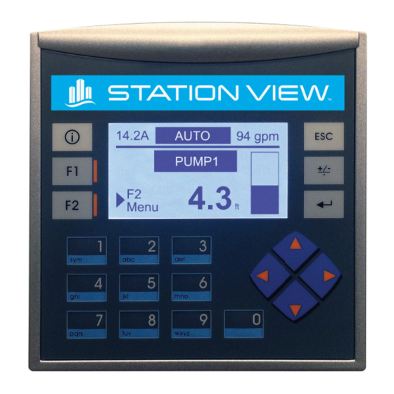
Page 5: Main Screen
PROGRAMMING MAIN SCREEN The main screen gives the operator an overview of the lift station status. Level Transducer Mode Float Switches Mode PRIMEX Station View Controller User Manual ™ ®... -
Page 6: Keypad Operation
KEY PAD OPERATION The controller keypad is used for screen navigation and data entry PRIMEX Station View Controller User Manual ™ ®... -
Page 7: Main Menu Navigation
MAIN MENU NAVIGATION Navigation from the Main screen to the Menu Screens. Press to go back to the previous screen at any time. PRIMEX Station View Controller User Manual ™ ®... -
Page 8: Active Alarms
Power loss or Phase loss to the control panel Check incoming power and phase loss monitoring setting (if used) ILLEGAL ENTRY Unauthorized personnel are tampering with Control access to the control panel the control panel PRIMEX Station View Controller User Manual ™ ®... -
Page 9: Alarm History
The Alarm History of the control panel can be accessed via the Alarm Menu. The last 14 alarm events are recorded with time and date stamp. The last alarm recorded is displayed first. Use the to view previous alarms. Press to go back to the previous screen at any time. PRIMEX Station View Controller User Manual ™ ®... -
Page 10: Alternation
If 1-2 is selected, P1 will start every time, and P2 will only be used as a lag pump. If 2-1 is selected, P2 will start every time, and P1 will only be used as a lag pump. Press to go back to the previous screen at any time. PRIMEX Station View Controller User Manual ™ ®... -
Page 11: Datalog
DATALOG The Station View™ controller will log daily station data for 7 days + today’s data since midnight. This data is very useful for tracking high in-flow events and pump performance. Cyc = number of cycles (pump starts) min = pump run time in minutes... -
Page 12: Set Levels
Note: There are 2 digital inputs on the StationView for High Level and Low Level floats. These inputs are only for monitoring and do not control the pumps. An external controller is the only way to the control the pumps in the event of a Station View controller failure... -
Page 13: Simulate
Caution: Pump will start and stop while using this function. Pump dry run is possible if no backup floats are used or by-passed. Note: the level simulation screen will time out after 10 seconds of inactivity and return to the measure level. PRIMEX Station View Controller User Manual ™ ®... -
Page 14: Advanced Setup Navigation
ADVANCED SETUP (MENU NAVIGATION) Press to go back to the previous screen at any time. PRIMEX Station View Controller User Manual ™ ®... -
Page 15: System & Sensor
SYSTEM (ADVANCED SETUP) The Station View controller can be configured to operate using a 4-20mA level transducer with 2 ™ backup float switches or with 4 float switches and no transducer. See the electrical schematic for sensor connections. SENSOR (ADVANCED SETUP) Entering the measuring range of the level transducer. -
Page 16: Flow
FLOW MONITORING (ADVANCED SETUP) Volumetric flow measurement is available when a level transducer is used for continuous level sensing in a tank. The Station View unit calculates the volume of liquid based on the level. The flow ™ is calculated by using the volume and the fill/discharge times. The in-flow and the discharge flow is measured. -
Page 17: Flow (Continued) & Amps
FLOW MONITORING (ADVANCED SETUP) (Continued) AMPS (ADVANCED SETUP) Entering the measuring range of the current transducer. The Station View controller uses a single current sensor input for multiple pumps. It combines the ™ pump run input with the current signal to determine the current for each pump. The measuring range of the current transmitter is typically listed on the device. -
Page 18: Dry Run & High Amp
Screen and close the general alarm relay. This fault does not stop the pump, it is an alarm only. Set to 0.0 A to disable this alarm function. PRIMEX Station View Controller User Manual ™... -
Page 19: Date/Time, Max Run Time, Password & Pump Data
PUMP DATA (ADVANCED SETUP) The Pump Data screen is for information only. It is a record of the pump HP, Volts and FLA. This data can be viewed remotely when connected to the Primex Pump Watch cellular monitoring ™... -
Page 20: I/O Status
PUMP 1 FAULT (USER) RELAY NO RELAY C PUMP 2 FAULT (USER) PUMP 2 FAULT (USER) RELAY NO TRANSISTOR HIGH LEVEL XDCR (USER) NOT USED TRANSISTOR LOW LEVEL FLOAT (XDCR MODE) - (USER) NOT USED PRIMEX Station View Controller User Manual ™ ®... -
Page 21: I/O Configuration, Dimensions & Mounting
I/O TERMINAL CONFIGURATION DIMENSIONS AND MOUNTING PRIMEX Station View Controller User Manual ™ ®... - Page 22 +1-844-4PRIMEX (477-4639) WWW.PRIMEXCONTROLS.COM PN 1038494D 10/20 © 2018 SJE, Inc. All Rights Reserved. PRIMEX is a trademark of SJE, Inc.
Need help?
Do you have a question about the STATION VIEW and is the answer not in the manual?
Questions and answers