Table of Contents
Advertisement
Quick Links
Advertisement
Table of Contents

Related Manuals for GE GL 310 F3/4031 P/VR


Summary of Contents for GE GL 310 F3/4031 P/VR
- Page 1 Operating Instructions No. 248 (EN) Device: High Voltage Circuit Breaker GL 310 F3/4031 P/VR GL 311 F3/4031 P/VR GL 312 F3/4031 P/VR GL 313 F3/4031 P/VR Manufacturer: GE Grid GmbH Lilienthalstrasse 150 - 34123 Kassel, Germany REV6 OI 248 (EN)
-
Page 3: Table Of Contents
TABLE OF CONTENT Introduction ......... . Safety . - Page 4 TABLE OF CONTENT 7.1.1 Connecting the Cable..........7.1.2 Checking the Operating Points of the density monitor .
- Page 5 TABLE OF CONTENT 10.1.2 Removing the Double Motion System ....... . 10.1.3 Removing the Guide Shaft .
- Page 6 TABLE OF CONTENT Replacement Parts and Accessories ..... . 117 A3.1 Servicing Equipment ..........A3.2 Replacement of Arcing Contacts .
-
Page 7: Introduction
The operational reliability of the equipment is guaranteed by proper servicing and by following the instructions given in this manual. GE assumes no liability for da- mage due to failure to follow the manual instructions. - Page 8 Documents in whole or in part without the prior written permission of General Electric Company. Trademark Notices GE and GE Logo are trademarks and service marks of General Electric Company. IEC is a registered trademark of Commission Electrotechnique In- ternationale.
- Page 9 NTRODUCTION Това оборудване съдържа флуориран парников газ (SF ), обхванат в Протокола от Киото, който има потенциал за глобално затопляне (ПГЗ) 22200. SF трябва да се улавя, а не да се изпуска в атмосферата. Повече информация относно използването и боравенето с SF ще...
- Page 10 NTRODUCTION OI 248 (EN) REV6 /REV6...
-
Page 11: Safety
AFETY Safety Safety Instructions The operator of the high voltage switchgear described in this manual must make sure • that work on high voltage switchgear is carried out solely by qualified personnel; • that work complies with electrical codes and standards; •... - Page 12 AFETY OI 248 (EN) REV6 /REV3...
-
Page 13: Handling Sulfur Hexafluoride
ANDLING ULFUR EXAFLUORIDE Handling Sulfur Hexafluoride Sulfur hexafluoride (SF ) is an inert gas that is colorless and odor- less, chemically neutral, non-combustible and approximately five times heavier than air. It is non-toxic and is not an ozone-depleting substance. Pure SF is completely safe for human beings and animals physio- logically. -
Page 14: Frostbite
ANDLING ULFUR EXAFLUORIDE 3.1.3 Frostbite If compressed SF escapes quickly, the sudden expansion lowers its temperature. The gas temperature can drop substantially below 0°C. A person accidentally exposed to a gas jet may suffer severe frostbite. Therefore always wear safety goggles, leather gloves and appropriate work clothes when carrying out procedures involving components filled with SF - Do not eat, drink, smoke or store food in rooms containing SF... -
Page 15: Safety Precautions When Handling Used Sf6
ANDLING ULFUR EXAFLUORIDE Safety Precautions When Handling Used SF gas used in electrical equipment may contain decomposition products with toxic properties if it has been subjected to arcs. The- se decomposition products may exist in either a gaseous state or in the form of a powder. -
Page 16: Transport At The Installation Site
ANDLING ULFUR EXAFLUORIDE Transport at the Installation Site All pressure specifications are given in terms of relative pressure CAUTION Pole columns are shipped at a gas gauge pressure of approxima- tely 0.03 MPa (p ) (0.3 bar). The bursting of pressurized parts such as insulators or bushings may result in property damage or personal injury. -
Page 17: Components Supplied
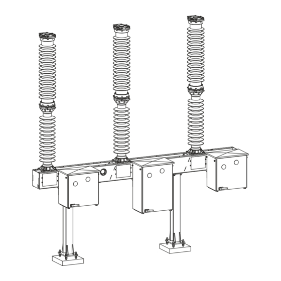
OMPONENTS UPPLIED Components Supplied Scope of Supply (Standard) The shipment for each circuit breaker includes the following compo- nents: Operating mechanism Pole column Crate containing accessories Base frame REV6 OI 248 (EN) 17 / 140 /REV1... -
Page 18: Scope Of Supply (Optional)
OMPONENTS UPPLIED Scope of Supply (Optional) Neither the supports nor the gas for the circuit breaker are included in the scope of supply. If desired, these components can be orde- red separately. Support Gas cylinder OI 248 (EN) REV6 18 / 140 /REV1... -
Page 19: Transport And Storage
RANSPORT AND TORAGE Transport and Storage Transport and Handling Improper handling of the transport units may result in serious damage. WARNING Therefore: - Comply with handling markings and labeling. - Use hoisting equipment with adequate load-bearing capacity. - Do not stand under suspended loads. The transport units are provided with handling markings and labeling. -
Page 20: Storage
RANSPORT AND TORAGE The wood used for the packaging may be chemically or thermally treated in order to prevent the spread of wood pests. Related rules and markings are defined in U.N. International Plant Protection Convention (IPPC) guidelines. IPPC-Symbol: Treated wood packaging Storage... -
Page 21: Installation
E-Mail: checkliste.kassel@alstom.com The checklist is part of the warranty agreement between the cus- tomer and GE Grid GmbH. In the event of a warranty claim, the warranty claim may be reduced or declined if the completed checklist is not on file at GE Grid GmbH. - Page 22 NSTALLATION Checklist for Installation and Commissioning Circuit Breaker Data Type & Serial No.: Customer: Station: Installation No. Operation to Be Performed Section Safety instructions have been carefully read and are under- stood Materials provided by station checked for completeness Shipment checked for completeness and lack of damage shipping pressure in each pole column checked 6.4.2 Component serial numbers checked for agreement...
- Page 23 Count shown on operations counter recorded 7.6.10 Testing and measuring equipment removed 7.6.11 Please send one completed and signed copy of the checklist to: GE Grid GmbH, Service Germany, Lilienthalstrasse 150, 34123 Kassel, Germany Fax: +49 561 502-2774, E-Mail: checkliste.kassel@alstom.com Place Date Stamp...
-
Page 24: Materials And Equipment To Be Provided By Customer
Unpacking the Transport Units Check the transport units for completeness and lack of damage. In the event of shipping damage, notify the freight forwarder and your authorized GE representative immediately. Improper handling of the transport units may result in serious damage. -
Page 25: Pole Column
NSTALLATION 6.4.2 Pole Column The pole columns can be equipped with two different types of insu- lators: composite or porcelain insulators. This means that they need to be handled differently. The two types of insulators can be identified as follows: Composite insulators - Flexible sheds Oil and cleaning additives attack the silicone surface of the insu-... -
Page 26: Unpacking Pole Column With Composite Insulators
NSTALLATION 6.4.2 a Unpacking Pole Column with Composite Insulators Attaching lifting tackle to the silicone surface can damage the in- sulator. CAUTION Therefore: - Attach lifting tackle solely to the fastening points provided (on the lower post insulator flange and the upper terminal pad mounting plate). -
Page 27: Unpacking Pole Column With Porcelain Insulators
NSTALLATION 6.4.2 b Unpacking Pole Column with Porcelain Insulators • Place two squared timbers on the ground as supports for the pole column. The pole column must be deposited on the lowermost and uppermost insulator flange, and the squared timbers must be spaced accordingly. - Page 28 NSTALLATION Checking the SF Shipping Pressure The pole columns are filled with SF at 0.3 bar for shipping purpo- ses. This means that the pole columns do not need to be evacuated during commissioning. If a pole column is no longer at the correct shipping pressure upon installation, this may indicate shipping damage to the pole column.
- Page 29 NSTALLATION T116 Gas coupling Screw cap Poppet valve REV6 OI 248 (EN) /REV5...
-
Page 30: Preinstalling The Supports
NSTALLATION Preinstalling the Supports Each support is fastened with four anchor bolts. Each anchor bolt has three nuts and two washers. The support is adjusted using the two lower nuts. The support is secured using the upper nut. One washer each is placed between the support and the nut immedia- tely below and above it. -
Page 31: Installing The Base Frame And Operating Mechanisms
NSTALLATION Installing the Base Frame and Operating Mechanisms • Check the base frame serial number, which is located on a sticker on the base frame itself. • Check to make sure the serial number agrees with the breaker serial number. •... -
Page 32: Preparing The Operating Mechanisms
Closing spring indication: "Spring discharged" Mechanism position: "OPEN" / "0" If this is not the case, do not trigger or operate the mechanism under any circumstance. GE Service must be notified. 6.7.1 Removing the Transport Lock Remove the right-hand side panels from the mechanisms. - Page 33 NSTALLATION Operating mechanism Side panel Roof Tooth lock washer Hexagon nut, M8 A2-70 Hexagon bolt, M6 A2-70 REV6 OI 248 (EN) /REV5...
-
Page 34: Installing The Pole Columns
NSTALLATION Installing the Pole Columns The operations described in this section must be carried out in se- quence for each of the three pole columns. The poles themselves can be installed in any order desired. 6.8.1 Erecting the Pole Columns The filling connection (2) of the pole column (1) must face up- ward during the erection procedure. -
Page 35: Positioning The Pole Columns
NSTALLATION • Hoist the pole column to an upright position, carefully rolling it on the rounded crankcase end. 6.8.2 Positioning the Pole Columns • Find the proper pole position on the base frame (A, B or C as viewed from the mechanism side; see illustration) and place the pole column in this position above the base frame. - Page 36 NSTALLATION Pole column Base frame Washer, 16 A2 Hexagon bolt, M16x55 8.8 TZN Hexagon nut, M16 A2-70 Tire lever Not supplied The opening springs are located in the crankcases of the pole co- lumns. The opening springs fix the pole columns in open position. All other installation steps are based on this open position of the pole columns.
-
Page 37: Aligning And Connecting The Pole Columns
NSTALLATION Aligning and Connecting the Pole Columns The pole column shafts are connected to the levers via a square profile. The levers can therefore only be mounted in four positions. No additional positioning aids are required. The tolerance allows for a slight clearance between the levers and the shafts. -
Page 38: Connecting The Drive Rod To The Drive Lever
NSTALLATION 6.10.1 Connecting the Drive Rod to the Drive Lever The drive rod and drive lever were already connected at the factory. 6.10.2 Connecting the Operating Mechanisms and Pole Columns The following operations must be carried out in sequence for each of the three pole columns. - Page 39 NSTALLATION • Brace the tire lever (16) against the side of the base frame or support and push the pole column until the holes in lever (6) and the drive rod (5) are aligned. Lubricate the flanged coupling pin (14) as per L2. The flanged coupling pin (14) must slide in easily. •...
-
Page 40: Mounting The High Voltage Terminal Pads
NSTALLATION 6.11 Mounting the High Voltage Terminal Pads The high voltage terminal pads are shipped in the box containing the accessories. The high voltage terminal pads may be mounted either on the front or the rear of the circuit breaker, as desired. Oxide films can form on the terminal pad mounting plates and the high voltage terminal pads during transport and storage, and these films can result in higher contact resistances. -
Page 41: Connecting The Cables
NSTALLATION 6.12 Connecting the Cables Improper connection of cables can pose a threat to personnel and system safety. DANGER The individual responsible for safety must give approval for con- necting the cables. When connecting the cables after filling the circuit breaker to rated pressure, there is the danger that insulators will burst if DANGER they have been damaged. -
Page 42: Earthing (Grounding) The Circuit Breaker
NSTALLATION 6.13 Earthing (Grounding) the Circuit Breaker The base frame and supports are equipped with earth connections (ground connections). Pole columns and operating mechanisms are conductively connected via their mounting points to the base frame and earthed or grounded through it (the earthing surfaces are shown in the dimensioned drawing). -
Page 43: Commissioning
OMMISSIONING Commissioning Serious personal injury or property damage can result during commissioning if the equipment is live or energized. DANGER Therefore: - Make sure that the circuit breaker is disconnected from the high voltage system. - Make sure the circuit breaker is earthed (grounded). The five safety rules of electrical engineering must be followed: - Disconnect the equipment from the power supply. -
Page 44: Checking The Operating Points Of The Density Monitor
OMMISSIONING 7.1.2 Checking the Operating Points of the density monitor In one equipment version, the switchgear is available with a den- sity monitor unit of type EasyCheck. The EasyCheck technology makes it particularly easy to perform the emission-free density monitor test in correspondence with the "F-gases regulation EU 517/2014"... - Page 45 OMMISSIONING • Connect the multimeter to the terminals for UW1 in the operating mechanism. • Slowly reduce the gas pressure in the piping until UW1 is reached. As you do so, compare the electric operating point with the density monitor indication. •...
-
Page 46: Filling The Pole Columns With Gas (Preparation)
OMMISSIONING Filling the Pole Columns with Gas (Preparation) The pressurized components of the pole columns can be damaged by improper handling. If the components are damaged, WARNING they may burst when the gas pressure is increased. This can re- sult in serious personal injury or property damage. Therefore: - Inspect the pole columns visually for damage before beginning the filling operation. -
Page 47: Establish Gas Connections Between Density Monitor And Pole Columns
OMMISSIONING 7.2.1 Establish Gas Connections between Density Monitor and Pole columns In one equipment version, the switchgear is available with a gas connection of type FlexLink. The FlexLink technology makes it particularly easy to couple the gas connections to the pole columns. (see Chapter “12.2” on page 101) We recommend that the following tools be used to connect the gas couplings:... -
Page 48: Filling The Breaker With Gas
OMMISSIONING Filling the Breaker with Gas All pressure specifications are given in terms of relative pressure CAUTION • Connect the filling hose of the gas-filling device (gas cylinder with pressure-reducing valve or gas handling cart) to the central supply connection (type DILO DN8 coupling). •... - Page 49 OMMISSIONING Liquid Gaseous t / °C (1)=Nominal Density 35,98 g/L (2)=Alarm Density 29,16 g/L (3)=Lockout Density 27,15 g/L (4)=Liquifaction Curve pressure curve -40°C (ND =0.46 MPa [p ] / UW1=0.36 MPa [p ] / UW2=0.33 MPa [p Rated pressure curve Alarm pressure curve Lockout pressure curve liquefaction curve...
-
Page 50: Checking The Anti-Condensation Heater
OMMISSIONING Checking the Anti-Condensation Heater Measure the resistance of the anti-condensation heater at the ter- minals in the operating mechanism and compare it with the referen- ce value in the routine test certificate. Enter the values in the checklist. Connecting the Supply and Control Cables Serious personal injury or property damage can result during commissioning if the equipment is live or energized. -
Page 51: Functional Testing
OMMISSIONING Functional Testing Operations at gas pressures below UW2 can result in mechanical damage to the circuit breaker. CAUTION Therefore: - Never operate the circuit breaker at gas pressures below UW2 (red area on the density monitor indicator). The pressurized components of the pole columns can be damaged by improper handling. -
Page 52: Measuring The Contact Resistance
OMMISSIONING 7.6.3 Measuring the Contact Resistance • Connect the measurement and supply leads to the high voltage terminal pads. • Measure the contact resistance (> 100A DC). • Compared the measured contact resistance with the reference values in the routine test certificate and enter it in the checklist. If the contact resistances are higher than the values given in the routine test certificate, repeat the measurement on the terminal pad mounting plate. -
Page 53: Checking Manual Operation
OMMISSIONING 7.6.5 Checking Manual Operation Manual operation bypasses any circuit breaker interlock system. Therefore: WARNING - Make sure that the gas pressure in the circuit breaker cor- responds at least to the UW2 value before beginning ma- nual operation. The manual operating levers are protected against accidental ope- ration by a locking plate. -
Page 54: Manually Charging The Closing Spring
OMMISSIONING 7.6.6 Manually Charging the Closing Spring • Check the operating state of the circuit breaker and the mechanism: - Closing spring discharged. - Breaker either in closed or open position. - Control voltage disconnected. • Open the door of the mechanism. •... -
Page 55: Checking The Anti-Pumping System
OMMISSIONING 7.6.7 Checking the Anti-Pumping System Type with Closing Priority (Standard) • Circuit breaker in open position: • Apply a continuous electrical opening command and at the same time give an electrical closing command: the circuit breaker will complete just one closing operation and one opening operation. •... -
Page 56: Operations Counter
OMMISSIONING 7.6.10 Operations Counter • Check the operation of the operations counter. • Read the count shown on the counter and enter the values in the checklist. 7.6.11 Final Tasks • Remove all testing and measuring equipment from the circuit breaker. -
Page 57: Troubleshooting
Work on the control system involves the danger of electric shock. Sudden movements of the charging system or the breaker linka- DANGER ge can cause serious injury. Troubleshooting tasks should be handled by qualified staff only. Such staff must follow the safety rules of electrical engineering. -
Page 58: Mechanism Reconditioning Procedures
ROUBLESHOOTING Mechanism Reconditioning Procedures 8.2.1 Replacing the Charging Motor • Disconnect both wires from the motor limit switch. • Unscrew the M6 mounting screws and remove the motor. • Install the new motor and tighten the mounting screws to a torque of 7Nm. -
Page 59: Replacing The Closing And Opening Coil
ROUBLESHOOTING 8.2.2 Replacing the Closing and Opening Coil • Disconnect the wire connections from the coil (3). Leaf spring Yoke Coil Side plate • Push aside the leaf spring (1) with your finger in the direction of the arrow. • Lift out the yoke (2) and place it on a clean surface. Remove the coil being replaced and insert a new coil over the side plates (4). -
Page 60: Replacing The Operations Counter
ROUBLESHOOTING 8.2.3 Replacing the Operations Counter • Detach the operating link (1). Operating link Operations counter • Remove the operations counter (2) by unscrewing the four M3 mounting screws. • Set the new operations counter manually to indicate the number of operations shown on the old operations counter (so that it will be possible later to determine the life of the breaker). -
Page 61: Replacing The Motor Limit Switch And/Or The Auxiliary Switch
ROUBLESHOOTING 8.2.4 Replacing the Motor Limit Switch and/or the Auxiliary Switch • Disconnect the wire connections to the motor limit switch (7) and/ or the auxiliary switch (5). Lever Drive rod Locking clamp Connecting rod Auxiliary switch Drive rod Motor limit switch •... - Page 62 ROUBLESHOOTING If the drum controller is positioned incorrectly, operation of the mechanism will be negatively affected. CAUTION Therefore check the position of the drum controller. - Motor limit switch: Contacts 15-16 are open in the "closing spring discharged" position. - Auxiliary switch: Contacts 15-16 are closed in breaker posi- tion "O".
-
Page 63: Replacing The Density Monitor
ROUBLESHOOTING Replacing the Density Monitor In one equipment version, the switchgear is available with a den- sity monitor unit of type EasyCheck. The EasyCheck technology makes it particularly easy to perform the emission-free density monitor test in correspondence with the "F-gases regulation EU 517/2014" quickly and safely. (see Chapter “12.1”... - Page 64 ROUBLESHOOTING Density monitor Threaded bushing Vent hole Filler block O-ring Check valve OI 248 (EN) REV6 /REV2...
-
Page 65: Austausch Einer Gasverbindung
ROUBLESHOOTING 8.3.1 Austausch einer Gasverbindung In one equipment version, the switchgear is available with a gas connection of type FlexLink. The FlexLink technology makes it particularly easy to couple the gas connections to the pole columns. (see Chapter “12.2” on page 101) The standard gas connection consists of bent tubes. - Page 66 ROUBLESHOOTING • Lubricate the threads of the junction points as per L4. • Insert the tubular stiffener and O-ring and screw the gas pipe together with the junction point until it is finger-tight. • Align the gas pipe and tighten it to a torque of 30Nm. OI 248 (EN) REV6 /REV2...
-
Page 67: Inspection And Maintenance
CAUTION Maintenance and reconditioning may only be performed by trained technicians. Qualified personnel can be requested from GE. The customer's staff can be trained at the manufacturer's plant. GE offers training courses for this purpose. REV6 OI 248 (EN) /REV3... - Page 68 Under certain operating conditions, such as operation of reactors and capacitor banks (especially back-to-back conditions), CAUTION reconditioning will be necessary after fewer operations. Special approval by GE is required for service under these condi- tions. 3,15 2500 1000...
-
Page 69: Ordering Accessories And Replacement Parts
NSPECTION AND AINTENANCE Ordering Accessories and Replacement Parts The following data are required for an order: - Type designation on nameplate - Serial number on nameplate - Instruction manual number on cover - Figure number and position number in the figure - Part description - Quantity required Inspection... -
Page 70: Maintenance
NSPECTION AND AINTENANCE Maintenance The circuit breaker must be shut down for maintenance work. Opening the pole columns is not necessary. • Disconnect the breaker from the high voltage system, and ground (earth) the breaker at both ends. • Discharge the closing and opening springs. This state is reached when the position indicator shows OPEN and the spring position indicator is on "discharged."... -
Page 71: Checking The Gas Quality
NSPECTION AND AINTENANCE 9.3.4 Checking the Gas Quality Take a gas sample and check for compliance with the limits. - Dew point: ≤ -5°C ≥ - SF conten - Acidity (SO < 180 ppmv 1) Based on the operating pressure and 20°C. 2) Measurements earliest perform three days after a short circuit. - Page 72 NSPECTION AND AINTENANCE OI 248 (EN) REV6 /REV3...
-
Page 73: Reconditioning
ECONDITIONING Reconditioning Danger due to electric shock. Therefore: DANGER - Disconnect the breaker from the high voltage system, and ground (earth) the breaker at both ends. Danger due to suddenly moving linkages. Therefore: DANGER - Discharge the closing and opening springs by carrying out closing and opening operations. -
Page 74: Reconditioning The Interrupter Chamber
ECONDITIONING The adsorption filter in each pole column that is opened must be re- placed. The period during which the gas compartments are open should be kept to a minimum. CAUTION The ingress of water (rain) must be prevented at all times. 10.1 Reconditioning the Interrupter Chamber 10.1.1... - Page 75 ECONDITIONING Interrupter chamber Upper flange of post insulator Coupling pin Splint pin 12KK2000 964 Hexagon screw, M12x65 A2-70 Washer, 12 A2 Max. gap 80 mm REV6 OI 248 (EN) /REV6...
-
Page 76: Removing The Double Motion System
ECONDITIONING 10.1.2 Removing the Double Motion System • Remove eight screws (3) and washers (4) from the upper flange of the chamber insulator (1). • Carefully remove the double motion system (2). Chamber insulator Double motion system Hexagon screw, M12x45 A2-70 Washer, 12x40 A2 OI 248 (EN) REV6... -
Page 77: Removing The Guide Shaft
ECONDITIONING 10.1.3 Removing the Guide Shaft • Remove the socket head cap screw (17) and the locking plate (18). • Remove the guide shaft (28) and space sleeve (21) from the fixed contact. • The interrupter unit is connected by the guide lever to the movable contact system. -
Page 78: Disconnecting The Making And Breaking Units
ECONDITIONING 10.1.4 Disconnecting the Making and Breaking Units • Remove the cotter pins (10) and flanged coupling pins (9) from the two guide levers. We recommend tool T101 for removing the cotter pins. • Pull the interrupter unit out of the movable contact system. Interrupter unit Movable contact system Guide lever... -
Page 79: Reconditioning The Fixed Contact
ECONDITIONING 10.1.6 Reconditioning the Fixed Contact • Replace the guide strip (12). The guide strip is located in a dovetail groove. It is therefore necessary to overcome mechanical resistance when replacing it. Guide strip, 3x5x380 (GK) 10.1.7 Lubricating the Interrupter Unit •... -
Page 80: Connecting The Making And Breaking Units
ECONDITIONING 10.1.8 Connecting the Making and Breaking Units The two lever arms of the guide lever are not identical. Matching them up with the guide rods is facilitated by an identification sys- tem. Identification System Guide lever Guide rod Movable contact system Dot mark Dot mark Interrupter unit... - Page 81 ECONDITIONING The two lever arms of the guide lever are not identical. Mismatching of rods and levers can result in damage to the pole CAUTION columns. Therefore: - Make sure you have correctly matched the rods and le- vers. - The lever arm for the double motion unit and the rod of the double motion unit are marked with dots.
-
Page 82: Mounting The Guide Shaft
ECONDITIONING 10.1.9 Mounting the Guide Shaft • Insert the interrupter unit (5) and the movable contact system (6) into the fixed contact (7) so that the shaft holes in the guide levers (8) and fixed contact (7) are lined up. •... -
Page 83: Reconditioning The Holder
ECONDITIONING 10.1.10 Reconditioning the Holder • Attach lifting tackle to the upper flange of the chamber insulator. • Loosen and remove two screws (17) on the lower flange of the chamber insulator (1). • Lift up the chamber insulator. • Replace the two guide strips (18). The guide strips are located in dovetail grooves. -
Page 84: Installing The Double Motion System
ECONDITIONING 10.1.11 Installing the Double Motion System • Clean the sealing and flange surfaces of the fixed contact (7) and grease them per lubrication specification L3. • Replace the formed gasket (19). • Move guide tool T102 above the connecting rods of the interrupter unit (5) and insert it into the interrupter tube. - Page 85 ECONDITIONING T102 Chamber insulator Double motion system Hexagon screw, M12x45 A2-70 Washer, 12x40 A2 Interrupter unit Movable contact system Fixed contact Holder Formed gasket 271 REV6 OI 248 (EN) /REV6...
-
Page 86: Adjusting The Double Motion System
ECONDITIONING 10.1.12 Adjusting the Double Motion System • Pull the interrupter unit down until it touches the stop (required tensile force approx. 200N). • Align the flattened sides of the connecting rod (31) so that they are parallel with the high voltage terminal pads (32). Alignment is accomplished by turning the interrupter unit. -
Page 87: Connecting The Interrupter Chamber To The Post Insulator
ECONDITIONING 10.1.13 Connecting the Interrupter Chamber to the Post Insulator The insulating tube in the post insulator must be in the closed posi- tion for this procedure. • Clean the sealing and flange surfaces of the holder (16) and grease them per lubrication specification L3. •... - Page 88 ECONDITIONING Holder coupling pin splint pin 12KK2000 964 Hexagon screw, M12x65 A2-70 Washer, 12 A2 Coupling piece Formed gasket 221 Insulating tube OI 248 (EN) REV6 /REV6...
-
Page 89: Replacing The Adsorption Filter
ECONDITIONING 10.1.14 Replacing the Adsorption filter In some cases, levers of the circuit breaker linkage may cover or conceal the filter cover. If this is the case, the levers must be remo- ved and remounted after the adsorption filter is replaced. •... -
Page 90: Final Operations
ECONDITIONING 10.1.15 Final Operations • Evacuate the breaker. • Fill the breaker with gas and check all seals for leakage (see “Filling the Breaker with Gas” on Page 48). 10.2 Disassembling the Post Insulator and Crankcase Requirements - The interrupter chamber has already been disconnected from the post insulator. -
Page 91: Disassembling The Opening Springs
ECONDITIONING 10.2.1 Disassembling the Opening Springs • Remove the filter cover. Remove the filter sleeve (48) and filter bag (65) from the crankcase. • Loosen the three screws (68). To do so, loosen the screws gradually one by one in order to prevent the spring guide (69) from tilting. -
Page 92: Disassembling The Crankcase
ECONDITIONING 10.2.2 Disassembling the Crankcase • Remove the four screws (64) and the bearing cap (44). • Remove the bearing insert (45) and the outer part of the cylindrical roller bearing. • Remove the shaft (43) and inner ring from the cylindrical roller bearing. - Page 93 ECONDITIONING Reassembly: • Replace all O-rings and gaskets. • Reverse the sequence to assemble the crankcase. • Insert a new filter bag (see “Replacing the Adsorption filter” on Page 89). The following instructions must be followed when assembling and installing the parts: CAUTION - Follow the specified lubrication procedure.
- Page 94 ECONDITIONING OI 248 (EN) REV6 /REV6...
-
Page 95: End-Of-Life Management
Compliance with the appropriate safety rules (see “Safety Precautions When Handling Used SF6” on Page 15) is required. Your local GE Service will be happy to answer any questions you may have about waste management. REV6 OI 248 (EN) - Page 96 ANAGEMENT OI 248 (EN) REV6 /REV2a...
-
Page 97: Special Equipment (Optional)
PECIAL QUIPMENT PTIONAL Special Equipment (Optional) This chapter describes only special equipment that is not part of the standard equipment of the switchgear. Special equipment is only available as option. 12.1 EasyCheck Density Monitor Unit The EasyCheck technology makes it particularly easy to perform the emission-free density monitor test in correspondence with the "F-gases regulation EU 517/2014"... -
Page 98: Functional Description
PECIAL QUIPMENT PTIONAL 12.1.1 Functional description The EasyCheck density monitor unit is equipped with an additional shut-off valve that permits separation of the pole column gas com- partments (G1) from the gas compartment of the density monitor and the central filling connection (G2) without loosening couplings or screws. -
Page 99: Operating Condition
PECIAL QUIPMENT PTIONAL 12.1.2 Operating condition The shut-off valve Q1 is open, the gas compartments (G1) and (G2) are connected to each other. The density monitor P1 monitors the gas in the switchgear gas compartments. The central fill cou- pling (X1) permits filling of the switchgear with gas or extraction of gas. -
Page 100: Test Condition
PECIAL QUIPMENT PTIONAL 12.1.3 Test condition The shut-off valve Q1 is closed, the gas compartments (G1) and (G2) are disconnected from each other. The density monitor P1 monitors only the gas pressure in the volu- me G2, but not the gas pressure in the switchgear gas compart- ments. -
Page 101: Flexlink-Gas Connection
PECIAL QUIPMENT PTIONAL 12.2 FlexLink-Gas Connection The FlexLink technology makes it particularly easy to couple the gas connections to the pole columns. The FlexLink gas connections consist of metal corrugated tubes that are elastic to ensure that the connection of the gas couplings to the pole columns is particularly easily possible. -
Page 102: If Flexlink Gas Piping Is Already Installed
PECIAL QUIPMENT PTIONAL 12.2.2 If FlexLink Gas Piping Is Already Installed To check all gas piping seals we recommend the use of the following tools: - T016: Compact open-end wrench (open-ended spanner), SW24 - WK001: Torque wrench (spanner) with ratchet adapter and SW27 open-end wrench head •... -
Page 103: Flexlink Gas Piping Still Needs To Be Installed
PECIAL QUIPMENT PTIONAL 12.2.3 FlexLink Gas Piping Still Needs To Be Installed To check all gas piping seals we recommend the use of the following tools: 30Nm T016 WK001 or T019 - T016: Compact open-end wrench (open-ended spanner), SW24 - WK001: Torque wrench (spanner) with ratchet adapter and SW27 open-end wrench head •... -
Page 104: Exchange Of Flexlink Gas Connections
PECIAL QUIPMENT PTIONAL 12.2.4 Exchange of FlexLink Gas Connections The flexible metal hose is fitted for sealing purposes with a sealing set consisting of a plastic bushing (1.1) flanked by two O-rings (1.2). For the sealing set to fit properly on the end of the flexible metal hose (1), two corrugation valleys (2) must remain uncovered. - Page 105 PECIAL QUIPMENT PTIONAL diagram 1 diagram 2 diagram 4 diagram 3 • Disconnect the gas coupling. This will disconnect the gas compartments of the poles from the gas piping. • Unscrew the screws (5) (see diagram 1). • Push the locking plates (2) to one side (diagram 2) •...
- Page 106 PECIAL QUIPMENT PTIONAL OI 248 (EN) REV6 /REV0...
-
Page 107: A1 Description Of The Equipment
ESCRIPTION OF THE QUIPMENT Description of the Equipment A1.1 Purpose Circuit breakers are used for power distribution in high voltage net- works. They are installed in substations along with other switchgear and are an essential functional and safety feature. In the event of a system disturbance or line fault, circuit breakers interrupt the resul- ting short-circuit currents within a few milliseconds. - Page 108 ESCRIPTION OF THE QUIPMENT The closing spring in the operating mechanism is charged by an electric motor via a gear unit for the purpose of storing the required operating energy. The main opening springs are located in the pole columns and are thus charged during each closing movement. The spring energy store contains enough mechanical energy to execute the O-CO operation, even if the motor power supply should fail.
-
Page 109: A2 Tools And Auxiliary Equipment
(grounding) conductors including terminals fasteners - Supports / lattice supports conforming to GE Grid GmbH drawings - High voltage terminal pads including fasteners - Gas for filling the breaker - Squared timbers and boards on which pole columns can rest before installation. -
Page 110: A2.4.1 Tool Recommendations
OOLS AND UXILIARY QUIPMENT A2.4.1 Tool Recommendations Tool Description Illustration T001 Torque wrench (spanner), 8-40Nm; 9x12mm seat; length <390mm T002 Torque wrench (spanner), 40-200Nm; 14x18mm seat T003 Torque wrench (spanner), 80-400Nm; 14x18mm seat T004 Ratchet adapter; can be used for ½" torque wrench;... - Page 111 OOLS AND UXILIARY QUIPMENT Tool Description Illustration T007 Socket set; ½" seat; consisting of: - Ratchet - Extensions - Sockets 10-34mm for hexagon bolts or screws 4-14mm for hexagon socket head screws T008 Flare nut wrench, 19mm; head for torque wrench (spanner); 9x12mm seat T009 Flare nut wrench, 24mm;...
- Page 112 OOLS AND UXILIARY QUIPMENT Tool Combinations Tool Illustration Comment WK001 WK001 (combined) For tightening gas cou- plings to specific torque WK001 (exploded view) T001 T006 T005 T023 T021 OI 248 (EN) REV6 /REV7...
-
Page 113: A2.5 Greases For Installation, Commissioning And Maintenance
OOLS AND UXILIARY QUIPMENT A2.5 Greases for Installation, Commissioning and Maintenance The following table describes how lubricating greases are to be used and applied. Each application is referred to in the text of the instruction manual by its abbreviation (e.g.: lubricated per L1). Abbre- Name Lubricating... -
Page 114: A2.6 Locking Adhesives For Installation, Commissioning And Maintenance
OOLS AND UXILIARY QUIPMENT A2.6 Locking Adhesives for Installation, Commissioning and Maintenance The following table describes how locking adhesives are to be used and applied. Each application is referred in the text of the instruc- tion manual by its abbreviation (e.g.: locked per S1). Abbre- Name of Locking Adhe- Function... -
Page 115: A2.8 Tools For Reconditioning
OOLS AND UXILIARY QUIPMENT A2.8 Tools for Reconditioning Tool Description Illustration T101 Assembly tool for cotter pins T102 Guide tool for interrupter unit T103 Blocking device: device for blocking the closing latch T104 Slow operation device: device for slow closing and opening operations T105 Ratchet box wrench (ring spanner) for... -
Page 116: A2.9 Auxiliary Materials And Supplies
OOLS AND UXILIARY QUIPMENT A2.9 Auxiliary Materials and Supplies Description Quantity Molykote BR 2 plus grease 0.20kg 0.40kg 0.80kg SF 1377 silicone grease 0.25kg 0.50kg Molykote PG 54 grease 1.00kg Locking adhesive 10cm³ Loctite 243 (blue) 250cm³ Alcohol for cleaning Scotch brand nonwoven... -
Page 117: A3 Replacement Parts And Accessories
CCESSORIES Replacement Parts and Accessories Replacement parts and accessories for circuit breakers can be purchased from the GE Service Germany. The replacement parts have been broken down into several recom- mended groups based on many years of experience. Replacement Parts List "R" = Always Recommended... -
Page 118: A3.1 Servicing Equipment
EPLACEMENT ARTS AND CCESSORIES Other Replacement Parts and Accessories Description Gas cylinder, 5kg Gas cylinder, 10kg Gas cylinder, 15kg Gas cylinder, 20kg Gas cylinder, 40kg gas refill set Leak detector Hl300 Density monitor* Socket outlet with earthing (grounding) contact Lighting attachment, door contact** Terminal UK 5 N 751 Ground (earth) terminal UK5N/USLKG10 Button temperature controller... -
Page 119: A3.2 Replacement Of Arcing Contacts
EPLACEMENT ARTS AND CCESSORIES A3.2 Replacement of Arcing Contacts The following replacement parts are required for replacing arcing contacts. The number of replacement parts refers to one pole co- lumn. Description Quantity Interrupter unit Flanged coupling pin, 6x24 Cotter pin, 8x1.2 Guide strip 3x5x398 Guide strip 3x5x380 Arcing contact pin... - Page 120 EPLACEMENT ARTS AND CCESSORIES OI 248 (EN) REV6 /REV5...
-
Page 121: A4 Handling Used Sulfur Hexafluoride
ANDLING ULFUR EXAFLUORIDE Handling Used Sulfur Hexafluoride Sulfur hexafluoride (SF ) can become contaminated when used in electrical equipment. Contamination can result from leaks, incomplete evacuation, partial discharges, decomposition caused by electric arcs and mechanical erosion. Used SF is a valuable recyclable material that must be reconditioned and re-used. - Page 122 ANDLING ULFUR EXAFLUORIDE OI 248 (EN) REV6 /REV2...
-
Page 123: A5 Technical Description
ECHNICAL ESCRIPTION Technical Description A5.1 Technical Data: Circuit Breaker Type GL 310-GL 312 Type GL 310 GL 311 GL 312 F3/4031 P/VR F3/4031 P/VR F3/4031 P/VR Rated voltage Rated normal current 3150 3150 3150 Rated frequency 50 / 60* 50 / 60* 50 / 60* Rated power-frequency withstand voltage 50 Hz, 1 min... -
Page 124: Technical Data: Circuit Breaker Type Gl 313
ECHNICAL ESCRIPTION A5.2 Technical Data: Circuit Breaker Type GL 313 Type GL 313 F3/4031 P/VR Rated voltage Rated normal current 3150 Bemessungs-Frequenz 50 / 60* Rated power-frequency withstand voltage 50 Hz, 1 min - To ground - Across open switching device Rated lightning impulse withstand voltage - To ground - Across open switching device... -
Page 125: A5.3 Technical Data: Spring Operating Mechanism
ECHNICAL ESCRIPTION A5.3 Technical Data: Spring Operating Mechanism Type FK 3-1 Motor for charging the closing spring Rated voltage (preferred values) - Direct voltage 60/110/125/220/250 *) - Alternating voltage 120/230 *) Allowable rated voltage deviation 85 to 110 % Vn Power consumption ≤... - Page 126 ECHNICAL ESCRIPTION OI 248 (EN) REV6 /REV3...
-
Page 127: A6 Slow Operation For Maintenance Purposes
PERATION FOR AINTENANCE URPOSES Slow Operation for Maintenance Purposes Introduction These instructions describe the following manual operations: • Executing a slow closing operation • Executing a slow opening operation Manual operations in accordance with these instructions are not necessary during installation work and during normal breaker ope- ration. - Page 128 PERATION FOR AINTENANCE URPOSES Safety in General • Any manipulations of the equipment that do not conform to instructions may endanger both the individuals performing the manipulations and the spring mechanism. • If manipulations are performed on the spring mechanism that are not in compliance with FK3-..
- Page 129 PERATION FOR AINTENANCE URPOSES Product Safety • If the spring mechanism is operated without the circuit breaker, the total energy stored within the spring mechanism will be converted. • The mechanism can be severely damaged as a result. Only operate the spring mechanism when the circuit breaker is connected.
- Page 130 PERATION FOR AINTENANCE URPOSES Preparing the Spring Mechanism for Manual Operations Preparing the Cabinet Then Cabinet is mounted horizontally; • Remove the side panels (1) mounted on rear panel • Remove the side panel lock nuts (2) • Swing the side panel (1) out and down Horizontal mounting configuration shown 1 Side panel...
- Page 131 PERATION FOR AINTENANCE URPOSES Then Spring mechanism has no under- Manual releases are normally voltage release locked. If this is not the case: Spring mechanism has under- • Loosen the M6 screws. voltage release and integrated • Slide manual release locking lokking device device (7) in the direction of the arrow until manual releases are...
- Page 132 PERATION FOR AINTENANCE URPOSES Locking the Undervoltage Releases • If the spring mechanism is equipped with undervoltage releases and if slow closing or opening operations are necessary, then the undervoltage release must be locked. Then Undervoltage release has no Insert hook of locking device (10) lokking device and pull out solenoid until it hits the stop;...
- Page 133 PERATION FOR AINTENANCE URPOSES Locking the Closing Latch if the Closing Spring is Charged • The closing latch may be actuated unintentionally when manipulations are being performed on the spring mechanism. • Performing manipulations on the spring mechanism when the closing spring is charged and the closing latch is not locked poses a risk of injury.
- Page 134 PERATION FOR AINTENANCE URPOSES Executing a Slow Closing Operation The spring mechanism is prepared for manual operations. Checking the Operating State of the Circuit Breaker and the Spring Mechanism Position of Position Indicator Spring position indicator shows clo- Breaker position indicator is sing spring is uncharged or charged in open position Tools Required...
- Page 135 PERATION FOR AINTENANCE URPOSES Installing the Slow Operation Device • Place the support plate (17) of the slow operation device (15) on the upper right spacer sleeve (18) and prop the device against the mechanism housing. • Attach the hook (19) of the slow operation device to the pin (20) of the support latch (21).
- Page 136 PERATION FOR AINTENANCE URPOSES Operating State after Slow Closing Position of Position Indicator Spring position indicator shows clo- Breaker position indicator is sing spring is uncharged or charged in closed position, opening spring is charged Removing the Slow Operation Device •...
- Page 137 PERATION FOR AINTENANCE URPOSES Installing the Slow Operation Device • Place the support plate (17) of the slow operation device (15) on the upper right spacer sleeve (18) and prop the device against the mechanism housing. • Attach the hook (19) of the slow operation device to the pin (20) of the support latch (24).
- Page 138 PERATION FOR AINTENANCE URPOSES Loosening the Manual Release Locking Device • Loosen the M6 screws. • Slide the manual release locking device (7) in the direction of the arrow. • Tighten the M6 screws. 7 Manual closing release 9 Manual release locking device 8 Manual opening release OI 248 (EN) REV6...
- Page 139 PERATION FOR AINTENANCE URPOSES Opening Manually • Release the opening latch (24) using the manual opening release (9). • At the same time, turn the nut (22) counterclockwise until the support latch (21) of the roller follower (23) has passed the opening latch (24).
- Page 140 PERATION FOR AINTENANCE URPOSES Removing the Slow Operation Device • Turn the hexagon nut (22) counterclockwise until enough pressure is removed from the hook (19) that the slow operation device (15) can be removed. Relocking the Manual Releases • Loosen the M6 screws. •...
Need help?
Do you have a question about the GL 310 F3/4031 P/VR and is the answer not in the manual?
Questions and answers