
Related Manuals for thermital AF UIH

Summary of Contents for thermital AF UIH
- Page 1 MANUALE D’INSTALLAZIONE INSTALLATION INSTRUCTIONS AF UIH Unità idronica Hydronic unit AF UIH 050 AF UIH 065 AF UIH 080 - 110 AF UIH 140...
-
Page 2: Table Of Contents
Gentile tecnico, ci complimentiamo con Lei per aver proposto un'unità idronica AF UIH, un prodotto moderno, in grado di assicurarLe il massimo benessere per lungo tempo con elevata affidabilità, efficienza, qualità e sicurezza Con questo libretto desideriamo fornirLe le informazioni che riteniamo necessarie per una corretta e più... - Page 3 IMPORTANTE! Leggere prima di iniziare l’installazione L’installazione di questi prodotti dovrà essere eseguita da personale qualificato ai sensi dei regolamenti Europei 303/2008 e 517/2014 Questo sistema deve seguire rigidi standard di sicurezza e di funzionamento Per l’installatore o il personale di assistenza è molto importante installare o riparare il sistema di modo che quest’ultimo operi con sicurezza ed efficienza Raccomandazioni •...
- Page 4 Se necessario, chiedi aiuto Queste istruzioni sono tutto quello che necessita per la maggior parte delle tipologie di installazione e manutenzione Nel caso in cui servisse aiuto per un particolare problema, contattare i nostri punti di vendita/assistenza per ulteriori informazioni In caso di installazione errata Il produttore non è...
-
Page 5: Generalità
Temperatura dell’acqua La temperatura dell’acqua massima ammessa all’ingresso è 75 ° C Volume dell’acqua del sistema (da verificare tassativamente) Minimo: AF UIH 050: 40 litri (*) AF UIH 065: 40 litri (*) AF UIH 080-110: 80 litri (*) AF UIH 140: 80 litri (*) Massimo: dimensionare il vaso di espansione dell’impianto in funzione del volume massimo dell’acqua,... -
Page 6: Presentazione
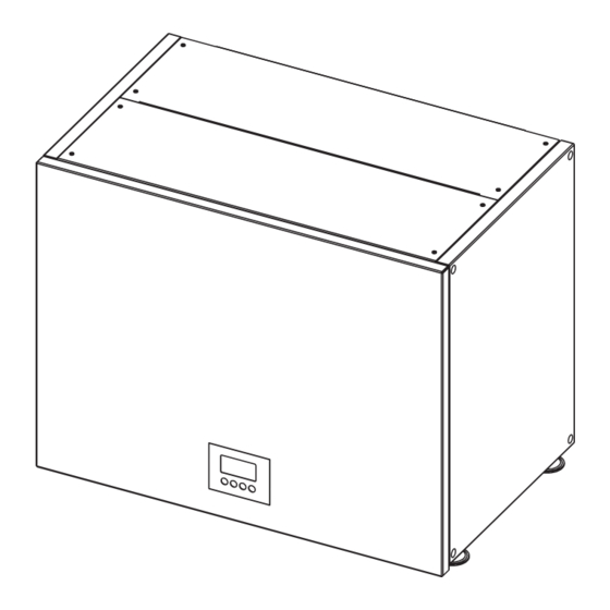
2 - PRESENTAZIONE 2.1 - DESCRIZIONE DELLE PARTI 1 - Scambiatore dell’acqua a piastre Materiali : 2 - Riscaldatore elettrico : 2 kW - Tubazioni in rame 3 - Valvola spurgo aria - Scambiatore dell’acqua acc inox 4 - Trasduttore di pressione acqua - Involucro in lamiera verniciata 5 - Termostato di sicurezza a riarmo automatico 6 - Termostato di sicurezza a riarmo manuale... - Page 7 2.2 - DIMENSIONI E PESI AF UIH 050 AF UIH 065 AF UIH 080-110 AF UIH 140 1 Collegamento entrata acqua 3/4” M 3/4” M 3/4” M 3/4” M 2 Collegamento uscita acqua 3/4” M 3/4” M 3/4” M 3/4” M 3 Raccordo ed evacuazione valvola di sicurezza ø...
-
Page 8: Installazione
2.3 - MATERIALE ADDIZIONALE PER L’INSTALLAZIONE (NON FORNITO) • Tubo in rame ricotto e disossidato per refrigerazione per il collegamento tra le unità ed isolato con polietilene espanso di spessore min 8 mm • Olio refrigerante per connessioni a cartella (circa 30 g ) •... - Page 9 ø 14 ø 8 ø 8 4 x ø 8 AF UIH Fig. 2 INSTALLAZIONE SOPRA AF ACS B • Appoggiare l’unità sopra AF ACS B, allineando i pannelli frontale e laterali • Massima altezza in abbinamento al modello AF ACS 220B : 1948mm •...
-
Page 10: Collegamenti
(6,35 mm) (6,35 mm) (9,52 mm) esterna 1/2” 1/2” 1/2” 5/8” ø Tubo gas (grande) Per AF UIH (12,7 mm) (12,7 mm) (12,7 mm) (15,88 mm) 140 Controllare in particolare le istruzioni Lunghezza tubazione minima di installazione Lunghezza tubazione massima dell'unità... - Page 11 4.2 - COLLEGAMENTO IDRAULICO 4.2.1 - COLLEGAMENTO ENTRATA E USCITA ACQUA • Collegare i tubi dell’acqua ai raccordi corrispondenti (per diametri e posizionamento, vedere pagina 6) E’ obbligatorio installare un filtro idraulico (1) (non fornito) all’entrata dell’acqua Collegarlo con due •...
- Page 12 4.3 - COLLEGAMENTO ELETTRICO Rimuovere il pannello frontale (fig.1) • NOTA: Il pannello é collegato tramite due cavi al quadro elettrico Fare attenzione a non tirare i cavi ed eventualmente disconnetterli Rimuovere il coperchio del quadro elettrico per accedere alle morsettiere (fig. 2) •...
-
Page 13: 5- Schemi Collegamenti Elettrici Del Sistema
Verificare il massimo carico elettrico supportato dell’interruttore magnetotermico (unità esterna + AF UIH) • Utilizzare il tasto ON/OFF sul pannello di controllo per spegnere l’unità • L’unità AF UIH deve essere sempre alimentata per permettere alle protezioni interne (es anti-freeze) di interve- nire ITALIANO... - Page 14 5.2 - CONFIGURAZIONE COMPLETA EXT. OUTDOOR UNIT DATALOGGER 1 MODBUS MODBUS GATEWAY DATALOGGER 1 DATALOGGER 2 OUTDOOR UNIT 5.3 - DETTAGLI CONNESSIONI • VALVOLA ACS (DHW VALVE) (1): Comando di chiusura valvola deviatrice Uscita fase 230 Vac / 20 W max (2): Neutro (3): Comando di apertura valvola deviatrice Uscita fase 230 Vac / 20 W max •...
- Page 15 • TERMOSTATO ON/OFF (THERMOSTAT ON/OFF) • Se switch SW3 (v pag 30) su scheda è impostato su 12 Vdc, collegare il contatto pulito del termostato tra i poli (9) e (10): (9): Ingresso bassa tensione (10): 12 Vdc Contatto chiuso: richiesta di riscaldamento/raffreddamento Contatto aperto: unità...
- Page 16 • CONTROLLORE ACS (DHW CONTROLLER) • Se switch SW3 (v pag 30) su scheda è impostato su 12 Vdc, collegare il contatto pulito del termostato tra i poli (13) e (14): (13): Ingresso bassa tensione (14): 12 Vdc Contatto chiuso: richiesta di produzione ACS / selezione setpoint secondario Contatto aperto: modalità...
- Page 17 • SONDA TEMPERATURA ESTERNA (OAT) INSTALLAZIONE SONDA TEMPERATURA ESTERNA PER FUNZIONAMENTO IN POMPA DI CALORE Questa sonda deve essere posta all’esterno in un luogo rappresentativo della temperatura da misurare (Parete Nord / Nord-Ovest) lontano da fonti di calore parassite (caminetto, ponte termico, ecc ) e al riparo dalle intemperie (per esempio sottotetto) NOTA: L’installazione di questa sonda è...
- Page 18 5.4 - ESEMPI DI COLLEGAMENTO FUNZIONAMENTO CON TERMOSTATO ON/OFF EXT. OUTDOOR UNIT DATALOGGER 1 MODBUS GATEWAY DATALOGGER 2 OUTDOOR UNIT FUNZIONAMENTO CON TERMOSTATO ON/OFF E CALDO/FREDDO (H/C) EXT. OUTDOOR UNIT DATALOGGER 1 MODBUS GATEWAY DATALOGGER 2 OUTDOOR UNIT NOTA: vedi paragrafo “MESSA IN FUNZIONE” sezione “IMPOSTAZIONE JUMPERS/SWITCH” - ABILITAZIONE MODALITA’...
- Page 19 FUNZIONAMENTO CON TERMOSTATO ON/OFF E CON SELEZIONE ECO EXT. OUTDOOR UNIT DATALOGGER 1 MODBUS GATEWAY DATALOGGER 2 OUTDOOR UNIT FUNZIONAMENTO CON TERMOSTATO ON/OFF, TERMOSTATO PER ACS E TERMOSTATO DI SICUREZZA EXT. OUTDOOR UNIT DATALOGGER 1 MODBUS GATEWAY DATALOGGER 2 OUTDOOR UNIT ITALIANO...
- Page 20 FUNZIONAMENTO SENZA TERMOSTATO EXT. OUTDOOR UNIT DATALOGGER 1 MODBUS GATEWAY DATALOGGER 2 OUTDOOR UNIT FUNZIONAMENTO SENZA TERMOSTATO + INTERRUTTORE DI SICUREZZA EXT. OUTDOOR UNIT DATALOGGER 1 MODBUS GATEWAY DATALOGGER 2 OUTDOOR UNIT ITALIANO...
- Page 21 FUNZIONAMENTO CON CONTROLLORE TEMPERATURA AMBIENTE 0 - 10V E PRODUZIONE ACS EXT. OUTDOOR UNIT DATALOGGER 1 MODBUS GATEWAY DATALOGGER 2 OUTDOOR UNIT FUNZIONAMENTO CON TERMOSTATO 24 Vac E PRODUZIONE ACS EXT. OUTDOOR UNIT DATALOGGER 1 MODBUS GATEWAY DATALOGGER 2 OUTDOOR UNIT ITALIANO...
-
Page 22: Schemi Impianto
6 - SCHEMI IMPIANTO ITALIANO... - Page 23 ITALIANO...
- Page 24 ITALIANO...
- Page 25 ITALIANO...
- Page 26 ITALIANO...
- Page 27 ITALIANO...
- Page 28 ITALIANO...
- Page 29 ITALIANO...
-
Page 30: Messa In Funzione
7 - MESSA IN FUNZIONE IMPORTANTE Prima di effettuare qualsiasi intervento sull’impianto, assicurarsi di aver tolto la corrente e vietato l’accesso all’installazione e alimentazione generale. Gli interventi devono essere effettuati da personale abilitato ad operare su questo tipo di macchina. 7.1 - VERIFICHE PRELIMINARI 7.1.1 - CIRCUITO IDRAULICO •... - Page 31 7.2 - IMPOSTAZIONE JUMPERS/SWITCH 7.2.1 - SCHEDA PRINCIPALE SPIE JUMPERS SWITCH SWITCH JUMPERS JP1 - ABILITAZIONE MODALITÀ RAFFREDDAMENTO CHIUSO: l’unità funzionerà in modalità solo riscaldamento (IMPOSTAZIONE DI FABBRICA) APERTO: l’unità può funzionare in modalità riscaldamento e raffreddamento Uso interno Non cambiare l’impostazione di fabbrica (APERTO) Se viene cambiata, l’unità non funzionerà...
- Page 32 7.2.2 - PANNELLO DI CONTROLLO/DISPLAY Vedere manuale “Pannello di controllo/display” per l’impostazione dei parametri del sistema ITALIANO...
- Page 33 7.3 - VERIFICHE COMPLEMENTARI CIRCUITO IDRAULICO (TRAMITE PANNELLO DI CONTROLLO) 7.3.1 - MESSA IN FUNZIONE FORZATA DELLA POMPA DI CIRCOLAZIONE Per realizzare le ultime verifiche del circuito idraulico, avviare la pompa di circolazione in marcia forzata nel modo seguente (impianto sotto tensione): - - - - - - - - •...
- Page 34 Q : 1.3 8 m 3 / h • Modificare la velocità della pompa per ottenere, a seconda dell’applicazione, la portata di lavoro nominale secondo la seguente tabella: Unità interna AF UIH AF UIH AF UIH AF UIH T uscita Applicazione acqua Unità...
- Page 35 PWM1 PWM = (100% - 75%) = 25% (25 3213/ 35 PWM1 • Sul grafico di AF UIH 065, incrociare la retta verti- PWM1 2730/ 45 cale corrispondente a 1 10 m /h con la curva della pompa corrispondente alla % PWM calcolata e la...
-
Page 36: Istruzioni Di Manutenzione
• Prima di qualsiasi intervento sull’impianto, accertarsi della messa fuori tensione e dell’interruzione dell’insieme delle alimentazioni. Prima togliere l'alimentazione all’unità esterna e poi all'unità idronica AF UIH o contemporaneamente. • Verificare inoltre lo scarico dei condensatori. • Gli interventi devono essere effettuati da personale abilitato ad operare su questo tipo di macchina. -
Page 37: Schema Elettrico
9 - SCHEMA ELETTRICO Colori dei cavi Simboli dei componenti Sensore pressione acqua Nero Marrone Sensore pressione gas Sonda temperatura ritorno acqua Verde Sonda temperatura mandata acqua Grigio Sonda temperatura aria esterna Arancione ICT1 Sonda uscita (CALDO) / ingresso (FREDDO) Rosa scambiatore a piastre Rosso... -
Page 38: Tabella Auto-Diagnosi
10 - TABELLA AUTO-DIAGNOSI PRECAUZIONE Disconnettere l’alimentazione e attendere che tutte le spie siano spente prima di operare nel quadro elettrico X SPIA SPENTA O SPIA ACCESA SPIA LAMPEGGIANTE DISPLAY SPIE SU SCHEDA DESCRIZIONE ERRORE DURANTE IL COLLAUDO ERRORE DI COMUNICAZIONE CON AF ACS B O KIT 2 ZONE ERRORE DI COMUNICAZIONE CON DISPLAY ERRORE SULL’UNITA’... - Page 39 Dear heating engineer, we would like to congratulate you on having recommended an hydronic unit AF UIH: a modern product that's capable of ensuring maximum comfort over time with a high degree of reliability, efficiency, quality and safety...
- Page 40 IMPORTANT! Please read before installation Installation of these products must be carried out by qualified personnel in accordance with European regulations 303/2008 and 517/2014 This system meets strict safety and operating standards For the installer or service person, it is important to install or service the system so that it operates safely and efficiently Recommendations •...
- Page 41 If necessary, get help These instructions are all you need for most installation sites and maintenance conditions If you require help for a special problem, contact our sale/service outlet for additional instructions In case of improper installation The manufacturer shall in no way be responsible for improper installation or maintenance service, including failure to follow the instructions in this document SPECIAL PRECAUTIONS •...
-
Page 42: Generalities
Water temperature The maximum allowable water inlet temperature is 75 ° C Water volume of the system (to be compulsorily checked) Minimum: AF UIH 050: 40 litres (*) AF UIH 065: 40 litres (*) AF UIH 080-110: 80 litres (*) -
Page 43: Presentation
2 - PRESENTATION 2.1 - DESCRIPTION OF THE PARTS 1 - Plate type heat exchanger Materials: 2 - Electric heater: 2 kW - Copper piping 3 - Air vent valve - Stainless steel water heat exchanger 4 - Water pressure transducer - Painted sheet metal cabinet 5 - Automatic reset safety thermostat 6 - Manual reset safety thermostat... - Page 44 2.2 - DIMENSIONS AND WEIGHT AF UIH 050 AF UIH 065 AF UIH 080-110 AF UIH 140 1 Water inlet connection 3/4” M 3/4” M 3/4” M 3/4” M 2 Water outlet connection 3/4” M 3/4” M 3/4” M 3/4” M 3 Safety valve connection and drainage ø...
- Page 45 2.3 - ADDITIONAL MATERIAL REQUIRED FOR INSTALLATION (NOT SUPPLIED) • Deoxidized annealed copper tube for refrigerant tubing connecting AF ACS B; it has to be insulated with foamed polyethylene (min thickness 8mm) • Anti-freeze oil for flare connections (about 30g ) •...
- Page 46 ø 8 ø 14 ø 14 ø 8 ø 8 AF UIH 4 x ø 8 Fig. 2 INSTALLATION ON AF ACS B • Place the unit on AF ACS B, aligning the front and side panels • Maximum height in combination with AF ACS 220B model: 1948mm •...
-
Page 47: Connections
1/2” 1/2” 5/8” ø Gas tube (large) (12,7 mm) (12,7 mm) (12,7 mm) (15,88 mm) For AF UIH 140 Check in particular the Minimum pipe length outdoor unit installation instructions Maximum pipe length without additional refrigerant SEE INSTALLATION INSTRUCTIONS Maximum pipe length with... - Page 48 4.2 - HYDRAULIC CONNECTION 4.2.1 - WATER INLET AND OUTLET CONNECTION • Connect the water pipes to the corresponding connections (for diameters and position, see page 6) It is mandatory to install a hydraulic filter (1) (not supplied) on the water intake Connect it using two •...
- Page 49 4.3 - ELECTRICAL CONNECTION • Remove the front panel (fig.1) NOTE: The panel is connected with two wires to the electrical junction box Be careful not to pull the wires and, in case, disconnect them Remove the cover of electrical junction box to access the terminal blocks (fig. 2) •...
-
Page 50: System Wiring Diagrams
DATALOGGER 2 OUTDOOR UNIT NOTES • Do not connect the power supply of AF UIH on the terminal block of outdoor unit • Connect the power supply under the same circuit breaker of outdoor unit • Check out maximum power input on circuit breaker (outdoor unit + AF UIH) •... - Page 51 5.2 - FULL CONFIGURATION EXT. OUTDOOR UNIT DATALOGGER 1 MODBUS MODBUS GATEWAY DATALOGGER 1 DATALOGGER 2 OUTDOOR UNIT 5.3 - CONNECTIONS DETAILS • DHW VALVE (1): DHW valve closing command Phase output 230 Vac / 20 W max (2): Neutral (3): DHW valve opening command Phase output 230 Vac / 20 W max •...
- Page 52 • THERMOSTAT ON/OFF • If switch SW3 (see page 30) of main board is set on 12 Vdc, connect thermostat dry contact between poles (9) and (10): (9): Low voltage input (10): 12 Vdc Closed contact: heating / cooling request Open contact: unit in standby •...
- Page 53 • DHW CONTROLLER • If switch SW3 (see page 30) of main board is set on 12 Vdc, connect thermostat dry contact between poles (13) and (14): (13): Low voltage input (14): 12 Vdc Closed contact: ACS production request / secondary setpoint selection Open contact: normal mode •...
- Page 54 • OUTDOOR TEMPERATURE SENSOR (OAT) INSTALLATION OF THE OUTDOOR TEMPERATURE SENSOR FOR HEAT PUMP OPERATION This sensor must be located outside in a location that is representative of the temperature to be measured (on a wall facing North / North-west) and located away from parasitic heat sources (chimney, thermal bridge, etc ) and sheltered from inclement weather (under a roof overhand, for example) NOTE: The installation of this sensor is optional •...
- Page 55 5.4 - CONNECTION EXAMPLES WORKING MODE SELECTION WITH ON/OFF THERMOSTAT EXT. OUTDOOR UNIT DATALOGGER 1 MODBUS GATEWAY DATALOGGER 2 OUTDOOR UNIT WORKING MODE SELECTION WITH ON/OFF THERMOSTAT AND HEAT/COOLING (H/C) EXT. OUTDOOR UNIT DATALOGGER 1 MODBUS GATEWAY DATALOGGER 2 OUTDOOR UNIT NOTE: see paragraph “STARTING”...
- Page 56 WORKING MODE SELECTION WITH ON/OFF THERMOSTAT AND ECO FUNCTION EXT. OUTDOOR UNIT DATALOGGER 1 MODBUS GATEWAY DATALOGGER 2 OUTDOOR UNIT WORKING MODE SELECTION WITH ON/OFF THERMOSTAT, THERMOSTAT FOR DHW AND SAFETY THERMOSTAT EXT. OUTDOOR UNIT DATALOGGER 1 MODBUS GATEWAY DATALOGGER 2 OUTDOOR UNIT ENGLISH...
- Page 57 WORKING MODE SELECTION WITHOUT THERMOSTAT EXT. OUTDOOR UNIT DATALOGGER 1 MODBUS GATEWAY DATALOGGER 2 OUTDOOR UNIT WORKING MODE SELECTION WITHOUT THERMOSTAT + SAFETY SWITCH EXT. OUTDOOR UNIT DATALOGGER 1 MODBUS GATEWAY DATALOGGER 2 OUTDOOR UNIT ENGLISH...
- Page 58 WORKING MODE SELECTION WITH 0 - 10V ROOM TEMPERATURE CONTROLLER AND DHW PRODUCTION EXT. OUTDOOR UNIT DATALOGGER 1 MODBUS GATEWAY DATALOGGER 2 OUTDOOR UNIT WORKING MODE SELECTION WITH 24 Vac THERMOSTAT AND DHW PRODUCTION EXT. OUTDOOR UNIT DATALOGGER 1 MODBUS GATEWAY DATALOGGER 2 OUTDOOR UNIT ENGLISH...
-
Page 59: System Layout
6 - SYSTEM LAYOUT ENGLISH... - Page 60 ENGLISH...
- Page 61 ENGLISH...
- Page 62 ENGLISH...
- Page 63 ENGLISH...
- Page 64 ENGLISH...
- Page 65 ENGLISH...
- Page 66 ENGLISH...
-
Page 67: Starting
7 - STARTING IMPORTANT NOTE Before carrying out any work on the installation, make sure that it is switched off and that access to it is prevented. Any work must be carried out by personnel qualified and authorised to work on this type of unit. 7.1 - PRELIMINARY CHECKS 7.1.1 - HYDRAULIC CIRCUIT •... - Page 68 7.2 - JUMPERS/SWITCH SETTING 7.2.1 - MAIN BOARD LEDs JUMPERS SWITCH SWITCH JUMPERS JP1 - ENABLING COOLING MODE CLOSED: the unit will run in heating mode only (FACTORY SETTING) OPEN: the unit can run in heating and cooling mode JP2 - DEFROST TYPE SELECTION Internal use Do not change factory setting (OPEN) If changed, the unit will not run properly JP3 - ENABLING COOLING MODE Internal use Do not change factory setting (OPEN) If changed, the unit will not run properly...
- Page 69 7.2.2 - CONTROL PANEL/DISPLAY See manual “Control panel /display” for the system parameterisation ENGLISH...
- Page 70 7.3 - ADDITIONAL HYDRAULIC CIRCUIT VERIFICATIONS (USING CONTROL PANEL) 7.3.1 - FORCED START-UP OF CIRCULATION PUMP To carry out the latest hydraulic circuit tests, start the circulation pump (forced start-up) as follows (under voltage system): - - - - - - - - •...
- Page 71 S P E E D : 8 5 % Q : 1.3 8 m 3 / h • Change the pump speed to obtain, depending on the application, the rated working capacity according to the following table: AF UIH 080- Indoor unit Water Application outlet t. Outdoor unit...
- Page 72 PWM = (100% - 75%) = 25% (25 PWM1 PWM1 3213/ 35 • On the AF UIH 065 chart, cross the vertical line PWM1 corresponding to 1 10 m /h with the pump curve 2730/ 45 corresponding to the calculated % PWM and the...
-
Page 73: Maintenance Instructions
• Before doing any work on the installation, make sure it is switched off and all power supplies locked out. Before disconnect the outdoor unit and then hydronic unit AF UIH or contemporally. • Also check that the capacitors are discharged. -
Page 74: Electrical Diagram
9 - ELECTRICAL DIAGRAM Symbols of the components Colour of the wires Water pressure sensor Black Brown Gas pressure sensor Blue Return water temperature sensor Green Supply water temperature sensor Grey Outdoor air temperature sensor Orange ICT1 Outlet sensor (HEAT) / inlet sensor (COOL) Pink plate exchanger Violet... -
Page 75: Auto-Diagnosis Table
10 - AUTO-DIAGNOSIS TABLE CAUTION Disconnect power and wait that all LEDs are OFF before servicing on the electrical box X LED OFF O LED ON LED BLINKING LEDs ON BOARD DESCRIPTION DISPLAY TEST MODE ERROR COMMUNICATION ERROR WITH AF ACS B OR 2 ZONE KIT COMMUNICATION ERROR WITH DISPLAY ERROR ON OUTDOOR UNIT REFRIGERANT PRESSURE SENSOR NOT CONNECTED... - Page 76 RIELLO S.p.A. Via Ing. Pilade Riello, 7 37045 - Legnago (VR) www.thermital.it Poiché l’Azienda è costantemente impegnata nel continuo perfezionamento di tutta la sua produzione, le caratteristiche estetiche e dimensionali, i dati tecnici, gli equipaggiamenti e gli accessori, possono essere soggetti a variazione.
Need help?
Do you have a question about the AF UIH and is the answer not in the manual?
Questions and answers