Table of Contents
Advertisement
Quick Links
Inertgas-Systems
§
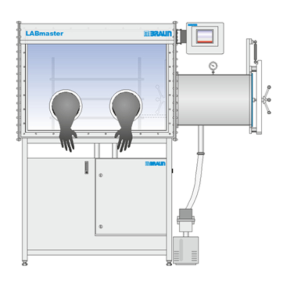
Workstation LABmaster pro sp / dp
§
Gas purifier MB-20-G / MB-200G-W
§
MOD box MB200MOD
with touch panel TP700
Operating Manual
Document number: 2611275-EN
Sales number: 1501101 ... 1501132 (LABmaster), 1500111 (MB-20-G), 1500114 (MB-200G-W), 1500050 ...1500092
(MOD Box)
V5.0 • 12/04/2018
Advertisement
Table of Contents


Need help?
Do you have a question about the LABmaster pro sp and is the answer not in the manual?
Questions and answers