Sign In
Upload
Manuals
Brands
MBRAUN Manuals
Laboratory Equipment
LABmaster pro sp
MBRAUN LABmaster pro sp Manuals
Manuals and User Guides for MBRAUN LABmaster pro sp. We have
1
MBRAUN LABmaster pro sp manual available for free PDF download: Operating Manual
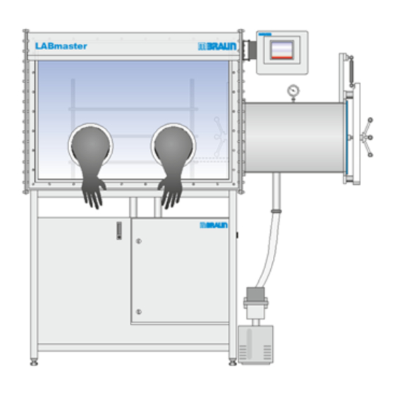
MBRAUN LABmaster pro sp Operating Manual (302 pages)
Workstation, Gas Purifier, MOD box
Brand:
MBRAUN
| Category:
Laboratory Equipment
| Size: 70 MB
Table of Contents
Table of Contents
3
General Information
11
Entries Referring to the System
11
Scope of Delivery
11
Type Plate
12
Liability
13
Warranty
14
Modifications
14
Service Address
14
Included Description of Optional Features
15
About this Operating Manual
16
General
16
Availability of Instructions
16
Safety Warnings in this Manual
16
Conventions Used in this Manual
17
Units Used
18
Terms Used
18
Abbreviations
19
Glossary
20
Disclaimer
21
Inert Gas Technology
23
Overview
23
Components
24
Glovebox
24
Antechamber
28
Gas Purifier
31
System Control
33
Vacuum Pump
35
Functional Description
36
Gas Flow General
36
Single Reactor Systems (Sp)
38
Optional: Double Purifier (Dp)
39
Optional: Solvent Filter
39
Box Pressure Control
41
Vacuum Antechamber
44
MBRAUN Standard Platforms
47
MB-20-G and MB-200G-W
47
Labmaster Pro Workstation
47
MOD Box Systems
48
Technical Data
48
Noise Level
50
On-Site Conditions
50
Safety
51
Intended Use
51
Improper Use
52
Statement of the Manufacturer
53
Qualification of Personnel
54
Duties of the Operating Personnel
54
Duties of the Operating Company
55
Behaviour in Case of Emergency
56
Process Materials
56
Classification and Assessment of Substances
56
MBRAUN-Hazard Classes
57
Examples of a Rough Classification
59
Safe Handling of Solvents, Chemicals and Gases
61
Controller
62
Gas Purifier Regeneration
62
Regenerative Solvent Filter
62
Residual Risks
62
Risk of Overpressure and Negative Pressure
62
Risk of Electrical Hazard
63
Risk of Suffocation
64
Risk of Combustion and Explosion
64
Risks When Operating a Damaged System
64
Risk of Environmental Damage
64
Safety Symbols Affixed to the Inert Gas System
65
Transport, Installation and Commissioning
69
Transport
69
Important Transport Labels
69
Storage Conditions
70
Long-Haul Carriage
70
On-Site Transport and Unpacking
70
Moving a Glovebox
72
Moving a Gas Purifier
74
Moving a Labmaster
76
Rolling the Equipment into Position
78
Installation
78
Definition of the Clean Room Volume
79
Preparing the Site
80
Media Supply Overview
82
System Cooling
88
Installation Vacuum Pump
89
Connecting the System
89
Installation of the Analysers
97
Final Inspection
98
Commissioning
98
Switching on the System
98
Inertisation of the Glovebox
99
Human Machine Interface
103
Introduction
103
Touch Panel
103
Explanation of Symbols and Colours
104
Start Screen
106
Screen Components
108
Functions Screens
108
Alarm Screen
109
Menu Screen Selection Screen
110
Parameter Screens
110
Trend Screens
111
Service Screen
112
User Level / Password Concept
115
Logon
115
Logout
116
Default Parameter Values
116
Operating Mode Principles
119
Service Book
119
Starting up the System
119
Gas Purifier Operating Modes
121
Glovebox Operating Modes
122
Antechamber Operating Modes
122
Shut down System
122
Gas Purifier Operation
125
Safe Operation
125
Parameter Limits
125
Select Regeneration Gas Hydrogen Concentration
125
Solvent and Solvent Filters
125
Navigation Overview
126
Purification Unit
126
Analysers
129
Regenerative Solvent Filter (Optional)
130
Circulation
132
Manual Activation and Deactivation
132
Automatic Circulation Activation
136
Solvent Filter Operation (Optional)
137
Manually Operated Solvent Filters (Activated Carbon Only)
137
PLC-Controlled Solvent Filters
138
Solvent Analyser (Optional)
140
Regeneration Operation
140
Regeneration Sequence
141
Reactor Regeneration
142
Solvent Filter Regeneration
145
ECO Mode
147
Overview
147
Glovebox Operation with the ECO Mode Feature
147
Regeneration
148
Dedicated Vacuum Pumps for Antechamber
148
Safety
149
Operation
149
Navigation
149
Parameters
150
Reduced Blower Speed
151
The Different Blower Speeds
152
Vacuum Pumps
153
Antechamber with Dedicated Vacuum Pump
153
Box Light
154
Glovebox or Enclosure Operation
155
Overview
155
Safe Operation
155
Overpressure Safety
156
Harmful or Hazardous Process Materials
156
Process-Related Particle Formation
156
Mechanical Hazards
157
Reactor Damage by Ambient Air
157
Inertisation
157
Working with Gloves and Glovebreaks
158
Monitoring Gas Concentration
159
Display H2O and O2 Concentration
159
Glovebox Trend Screen
160
Activation and Deactivation of Analysers
161
Analyser Operating Hours
162
Setting Glovebox Parameters
162
Activation / Deactivation of Glovebox Functions
164
Glovebox During Circulation
164
Glovebox Pressure
165
Rough Leakage Detection
166
Solvent Vapours in Glovebox Atmosphere
166
Glovebox During Regeneration
167
Glovebox Purge
167
Manually Start and Stop
169
Automatic Start and Stop
169
Additional Function and Equipment from MBRAUN
171
Additional Equipment
171
Additional Safety Equipment
172
Operating Company's Process Equipment
172
O2 and H2O Analysers
173
Overview of a O2 and a H2O Analyser
173
Safety
174
Intended Use
174
8A.2.2
174
Improper Use MB-OX-SE1
174
Improper Use of the Moisture Analyser
174
Oxygen Analyser
174
Description
174
Technical Data
175
Installing the Oxygen Analyser
175
Maintenance
176
Moisture Analyser
176
Description
176
Technical Data
177
Installing the Moisture Analyser
177
Maintenance for the H2O Analyser
178
Storing an MB-MO-SE1 Analyser
182
Mounting an Analyser
182
Disassembling or Replacing the Analyser
183
Returning Analysers to MBRAUN
184
8A.7.1
184
Return Service
184
8A.7.2
184
Returning a Faulty Analyser
184
Returning an Analyser for Calibration
186
Declaration about Decontamination.pdf
187
Freezer
189
Overview
189
Specifications
190
Operation
190
Antechamber Operation (Vacuum Antechamber)
193
Safe Operation
193
Vacuum Pump
194
Antechamber Door Operation
194
Main Antechamber
195
Mini Antechamber
196
Manual Loading and Unloading of the Mini Antechamber
198
Transferring Material in
198
Transferring Material out
200
PLC-Controlled Loading and Unloading
201
Parameters
204
Trend Curve
206
Antechamber Cycle Operation
206
Loading and Unloading
209
PLC-Controlled Door Interlock
209
Optional Antechamber Features
212
Additional Equipment
215
Introduction
215
Safety
215
Additional Options
215
Optional Glovebox Equipment
216
Optional Antechamber Equipment
218
Customer-Specific Components
218
Equipment from Other Manufactures
218
Mymbraun App
219
Setting up the Mymbraun App
219
Prerequisites
219
1.2 Preparatory Steps
219
1.3 Main Menu of the App
219
1.4 Registering
220
Functions
225
Settings
225
2.2 Monitoring
226
Information
229
Legal Notice
229
Account Information
229
Attachement
229
White Paper_Data Protection.pdf
229
Troubleshooting
235
Eliminating Faults
235
Plc
235
Gas Purifier
235
Glovebox
235
Antechamber
237
Stack Light (Optional)
238
ACK Warning and Alarm Messages
238
Acknowledgement of a Message
238
Deletion of a Warning Message
239
Definition of Alarm and Warning Messages
239
Failure During Regeneration
252
Cancellation or Power Failure
252
Regeneration of an LMF
252
Leak Test
252
Maintenance
253
Introduction
253
Document Inspection and Maintenance
253
Spare Parts Kit
254
Who May Do What
254
Qualification of Maintenance Personnel
254
Maintenance Plan Overview
255
System in General
255
Non-Regenerative LMF
255
Regenerative LMF
256
Gloves
256
Mini Antechamber
256
Main Antechamber
257
Vacuum Pump
258
Gas Purifier
258
Glovebox
259
Maintenance Contract with MBRAUN
260
Analyser Calibration
260
Safety E-Check Service
260
Safety During Maintenance Work
260
Preparations for Inspection and Maintenance Work
261
Shut down and De-Energization
261
General Advice for Maintenance Work
262
Maintenance Works
263
Glovebox
263
Gloves
264
Particle Filter
268
Calibrating and Cleaning Analysers
269
Antechamber
269
Reactor
269
Vacuum Pump
270
Non-Regenerative LMF (Optional)
270
Optional and 3Rd Party Components
272
Completing Maintenance
272
Returning Components for Service Purposes
273
Decommissioning
273
Annex
274
Declaration about Decontamination.pdf
274
Spare Parts
277
Introduction
277
Gas Purifier
277
Rear View
278
Box Purge Function (Optional)
280
ECO Mode
280
Solvent Filter (Optional)
281
Glovebox
283
Chassis and Lighting
283
Gloves and Glove Parts
283
Particle Filter
286
Analyser
286
Antechamber
287
Main Antechamber, ∅ 390
287
Mini Antechamber Ø 150 MM
288
Vacuum Pump
288
Oil Sealed Vacuum Pump
288
Dry Vacuum Pump
289
Touch Panel TP700
289
Foot Switch
290
3Rd Party Documentation
291
List of Attached 3Rd Party Documentation
291
Certificates
293
Declarations
293
Electrical and Wiring Diagram(S)
297
Safety
297
Basic Rules for Working with Electrical Systems
297
Electrical Safety Check
297
Advertisement
Advertisement
Related Products
MBRAUN LABmaster pro dp
MBRAUN EasyLab
MBRAUN LABmaster 130
MBRAUN MB 120B-G
MBRAUN MB 150B-G-I
MBRAUN MB 30G
MBRAUN MB-200G-W
MBRAUN MB-20G
MBRAUN MB200MOD
MBRAUN SPS 800
MBRAUN Categories
Laboratory Equipment
Desktop
More MBRAUN Manuals
Login
Sign In
OR
Sign in with Facebook
Sign in with Google
Upload manual
Upload from disk
Upload from URL