
Related Manuals for MBRAUN SPS-System


Summary of Contents for MBRAUN SPS-System
- Page 1 SPS-Systems Solvent Purification System SPS Compact SPS Manual-5 Technical Manual Original SPS Compact SPS Manual-5 Operating Manual SPS- Systems © GmbH – Version 4..3 – 06/2010...
- Page 3 Content SPS- Systems SPS Compact and SPS 800 Manual Operating Manual General Information Safety Installation System Description: Working Station System Description: Solvent Reservoir and Sampling Flask Operating: SPS Compact and Manual SPS 800 Maintenance Trouble Shooting Specification Spare Parts List Third Party List Operating Manual SPS-Systems ©...
-
Page 5: Table Of Contents
1. General Information General Information ................2 Entries Referring to the System ............2 Scope of Delivery ................3 Liability ....................3 Warranty ..................... 3 Modifications ..................4 Transport .................... 4 Storage ....................5 Conventions Used in this Manual ............. 5 1.10 Service Address ................. -
Page 6: General Information
Edition: ..................... Version 4.3 - 06/2010 (Original) See type plate for details Copyright: ..........© 2010 M. Braun Inertgas-Systeme GmbH (MBRAUN) Entries Referring to the System We guarantee the equipment as stated in the order/contract. This documentation is part of the system: Designation / Type: .................. -
Page 7: Scope Of Delivery
1. General Information Scope of Delivery The scope of delivery is defined by the acknowledgement of the order or as part of the contract. A complete standard solvent purification system consists of: SPS Compact SPS 800 Manual Solvent Purification Basic System for Solvent Purification System for 1 Solvent 5 various solvents... -
Page 8: Modifications
Warranty applies to a single unit and multi-unit system types. Modifications WARNING Danger of injury and damage! ► Changes and/or modifications of any kind to MBRAUN systems should be made by MBRAUN technicians only. Exceptions can be made with prior written confirmation from MBRAUN ►... -
Page 9: Storage
Marking of notices or additional information! 1.10 Service Address M. Braun Inertgas-Systeme GmbH Dieselstrasse 31 85748 Garching Germany Tel: +49 (0)89 32669-230 E-Mail: service@mbraun.de Fax: +49 (0)89 32669-235 Internet: www.mbraun.com Operating Manual MB-SPS Systems Page 1–5 © GmbH – Version 4.3 - 06/2010... - Page 10 1. General Information Page 1–6 Operating Manual MB-SPS Systems © GmbH – Version 4.3 - 06/2010...
- Page 11 2. Safety • SPS-Systems Safety Warnings ................. 2 2.1.1 Safety Warnings on the System ..............2 2.1.2 Safety Warnings in the Manual ............... 3 Safety Concept ................... 5 Intended Use ..................7 Improper Use ..................8 Basic Safety Instructions ..............9 2.5.1 General ......................
-
Page 12: Safety Warnings
2.1.1 Safety Warnings on the System The following symbols refer to MBRAUN components and parts. However, components and parts of sub-suppliers may show other symbols, not expressly mentioned or referred to in this manual. The following caution and command symbols may be seen on the system:... -
Page 13: Safety Warnings In The Manual
2. Safety • SPS-Systems 2.1.2 Safety Warnings in the Manual The safety warnings in the manual are marked according to European standards (98/37/EG, DIN EN ISO 12100-1, DIN EN 62079) as well as the ANSI (Z 535.6) standard. Marking of safety warnings adhering to European standards: Hazard! Indicates the possibility of very serious injury or fatality, and the possibility of considerable damage to property. - Page 14 2. Safety • SPS-Systems Marking of safety warnings adhering to the ANSI standard: DANGER Indicates an imminently hazardous situation that, if not avoided, will result in death, serious injury or serious damage to the system, other equipment or surrounding environment. WARNING Indicates a potentially hazardous situation that, if not avoided, could result in death, serious injury or serious damage to the system, other equipment or surrounding...
-
Page 15: Safety Concept
2. Safety • SPS-Systems Safety Concept Organic solvents are pushed through a solvent purification column by pressurizing a solvent reservoir with an inert gas – usually nitrogen. The system pressure is secured by a pressure relief valve to a maximum of 0.5 bar. An inert gas is used for pressurizing the system. Therefore during the intended use no gas mixture can be formed inside the system that could burn or explode. - Page 16 In case of failure of the exhaust ► interrupt operation of the SPS-System immediately! ► safeguard the SPS-System! Page 2–6 Operating Manual SPS- Systems ©...
-
Page 17: Intended Use
2. Safety • SPS-Systems Intended Use MBRAUN Solvent Purification System (SPS) is designed for removing moisture and oxygen from organic solvents and allows sampling of the purified solvents into a storage vessel, purged before with inert gas (e.g. Nitrogen). •... -
Page 18: Improper Use
2. Safety • SPS-Systems SPS Compact The working station of the system is supplied with a double filter column. A vacuum pump is necessary, but not part of delivery. SPS-800 Manual System The manually operated system of the SPS 800 consists of 5 parallel filter columns which can be utilized by the customer for selected solvents. -
Page 19: Basic Safety Instructions
► Maintenance work - other than that described in the chapters Trouble Shooting, Maintenance and Service and Spare Parts List - is only permitted to be performed by MBRAUN service personnel. 2.5.2 Emergencies... -
Page 20: On-Site Requirements
2. Safety • SPS-Systems 2.5.4 On-Site Requirements CAUTION Risk of injury and damage! For data on the on-site requirements, e.g. Ambient conditions Floor characteristics, floor loading capacity Mains electricity, compressed gas, cooling and other connections see Chapter 1.8. Storage and 3.1.3 Site Location 2.5.5 Observe the Operating Instructions WARNING... -
Page 21: Qualification Of The Personnel
2. Safety • SPS-Systems 2.5.6 Qualification of the personnel WARNING Risk of injury and damage! ► The personnel must be adviced in operating solvents and must be informed about the kind of appearing solvent vapours. ► As a matter of principle, working on the system without the personal protective equipment (PPE) stipulated in the operating instructions for this task is forbidden. -
Page 22: Disposal
Exhaust fumes: All exhaust fumes should be vented through an adequate disposal/ventilation system. MBRAUN is not responsible for pollution of the environment and resultant serious health problems. Page 2–12 Operating Manual SPS- Systems ©... -
Page 23: Hazards And Safety Measures
► During purging, ensure a good ventilation of the ambient air. Note: On request, MBRAUN can recommend a portable personal gas alarm instrument that alerts the operator to a reduction of oxygen content in the ambient air. -
Page 24: Electrostatic Discharge
2. Safety • SPS-Systems 2.6.2.1 Electrostatic Discharge DANGER Risk of damage or injury due to electrostatic discharge! Electrostatic discharge can occur while touching and working with plastic parts, hoses and pipes, wiring and the system as a whole. This can cause solvents and process chemicals to ignite when not within an inert gas atmosphere. -
Page 25: Solvents, Chemicals And Gases
2. Safety • SPS-Systems 2.6.3 Solvents, Chemicals and Gases Solvents, chemicals and gases used in the system are not supplied by MBRAUN. Any substances handeled within in the glovebox are provided and applied by the system user. DANGER Risk of damage or injury! Materials used may be flammable, explosive and/or toxic. -
Page 26: Danger Of Carcinogenic Fibre Dust
If the system meets any or all of the above: ► make it inoperable ► secure it against any unauthorized or unintentional operation ► contact the MBRAUN Service Department Page 2–16 Operating Manual SPS- Systems ©... - Page 27 Supply Piping for Vacuum Pump ..............9 3.2.6 Piping Solvent to Glove Box (optional for SPS 800 Manual) ........9 3.2.7 Grounding ........................9 3.3 Connecting the SPS-System ................10 3.3.1 General ........................10 3.3.1.1 Vakuum Pump ................... 10 3.3.1.2 Grounding of Electro Static Charging ............
-
Page 28: Installation And Commissioning Of The Solvent Purification System
Selecting the site for an MBRAUN system or any part of a multi-unit system should be carried out applying the following guidelines. If in doubt, contact the MBRAUN service department for assistance. Page 3–2 Operating Manual MB-SPS-System © GmbH – Version 4.3 - 06/2010... -
Page 29: Storing The Solvent Reservoir
► Refer to the safety sheets of the specific solvents and ► Make aware about potential cross reactions ► Always keep the solvent reservoirs under inert gas Operating Manual MB-SPS-System Page 3–3 © GmbH – Version 4.3 - 06/2010... -
Page 30: Installation And Commissioning
A final inspection and specification test is performed by a MBRAUN technician if the installation is made by MBRAUN. If the customer does the installation and first commissioning by himself, MBRAUN recommends performing a complete system and specification test prior to operating the system. -
Page 31: Media Connections
Connecting the working gas source with the Working Gas IN system connection. Material Optional (length as required): Either Ø 6 mm copper pipe or Ø 6 mm stainless steel pipe. Connection Ø 6 mm tube fitting. Type Operating Manual MB-SPS-System Page 3–5 © GmbH – Version 4.3 - 06/2010... -
Page 32: Solvent Connections (Sps 800 (Manual)
→ the use of Tetra Hydro Furan (THF) without stabilizer: Solvent quality, e.g. Sigma Aldrich (THF anhysrous 99.9% (inhibitor free) Art..No. 401757. → Purification with MB-KOL-M Type 2. Page 3–6 Operating Manual MB-SPS-System © GmbH – Version 4.3 - 06/2010... -
Page 33: Exhaust
> 4,2 m³/h Material Piping and disposal facility are provided and applied by the system user. Connection NW 75 for both connections. Type On request, you require a combined connection. Operating Manual MB-SPS-System Page 3–7 © GmbH – Version 4.3 - 06/2010... -
Page 34: Equipment For Vacuum Pump (Optional)
Refer to the safety concept in chapter 2.2 and to chapter 3.3.1! Note! - protected Dependend on the specific solvent in your system, an vacuum pump can be mandatory. Please, contact the service of MBraun. 3.2.5.1 Power Connection Vacuum Pump DANGER Hazardous electrical voltage! ►... -
Page 35: Supply Piping For Vacuum Pump
Ø 6 mm tube fitting Type 3.2.7 Grounding Potential equalization between system and surrounding Length 2,5 m Material green/yellow 4mm² copper cable Connection M8 ring type terminal type Operating Manual MB-SPS-System Page 3–9 © GmbH – Version 4.3 - 06/2010... -
Page 36: Connecting The Sps-System
3. Installation and Commissioning of the SPS Working Station Connecting the SPS-System 3.3.1 General CAUTION Risk of damage! Be carefully when handling gases and solvents! ► Care for keeping all technical and safety guidelines concerning exhaust air treatment! (E.g. VDMA 24169 and EN945-1 cat 3 in Europe) ►... - Page 37 ► Set pressure reducing valve 5 to 0,3 – 0,5 bar (30 – 50 kPa; 4,5 – 7,25 psi) secondary. Observe the pressure reading at the manometer above. Pressure Reducing Valve at the front of the working station (Valve 5) (see also chapter 4.2.1) Operating Manual MB-SPS-System Page 3–11 © GmbH – Version 4.3 - 06/2010...
-
Page 38: Sps Compact
( see chapter 3.3.5). 1 Connection Solvent 2 Pressure Connection Solvent 6 Main Grounding Connection 3.3.2.3 Exhaust SPS Compact ► It is mandatory, to install the SPS-Compact-System under a laboratory hood. Page 3–12 Operating Manual MB-SPS-System © GmbH – Version 4.3 - 06/2010... -
Page 39: Sps 800 Manual
Connection for working gas in (Nitrogen IN) Connection for vacuum pump Connection Purge hose (for purging of the system and purging of the solvent reservoirs) Operating Manual MB-SPS-System Page 3–13 © GmbH – Version 4.3 - 06/2010... - Page 40 Pressure indication for primary (top) pressure working gas (N Pressure indication for vacuum Connections for exhaust: Top exhaust outlet (NW75) Bottom exhaust Air INLET outlet (NW75) (do not block) Page 3–14 Operating Manual MB-SPS-System © GmbH – Version 4.3 - 06/2010...
-
Page 41: Connecting The Working Gas
Refer to chapter 2.6.2 ► In case of operating a SPS system with other systems, e.g. a Glove Box, ensure a potential equalization. ► Connect the grounding cable to house grounding. Operating Manual MB-SPS-System Page 3–15 © GmbH – Version 4.3 - 06/2010... -
Page 42: Commissioning
► If using open reservoirs, it is mandatory wearing personal protective clothes, such as protection goggles, according to the used solvent. Page 3–16 Operating Manual MB-SPS-System © GmbH – Version 4.3 - 06/2010... -
Page 43: Connecting And Inertising The System
► Fix it with the retaining clip. ► Tighten the retaining clip „hand tight“. 3. Connect the Nitrogen (N2) supply ► connect the gas supply hose and the purge hose → next page Operating Manual MB-SPS-System Page 3–17 © GmbH – Version 4.3 - 06/2010... - Page 44 According to the volume of the filter column and the kind of solvent it will take a longer period, until the solvent has permeated the filtrate and will leave at the tapping point. Page 3–18 Operating Manual MB-SPS-System © GmbH – Version 4.3 - 06/2010...
- Page 45 4. System Description Working Station Buildup and Components ..............2 4.1.1 General ......................2 Buildup SPS - Working Station ............3 4.2.1 SPS Compact ....................3 4.2.2 SPS 800 Manual ..................... 4 4.2.3 SPS 800 Automatic ..................5 Principle of the SPS-Solvent Purification ......... 6 4.3.1 Overview Functions of Hand Valves ...............
-
Page 46: Buildup And Components
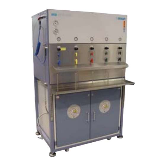
4. System Description Working Station Buildup and Components 4.1.1 General MBraun offers diverse types of SPS, performing different attainments: SPS Compact Double Filter Column; Manual Operation for one solvent SPS 800 Manual 5 parallel Filter Columns; Manual Operation up to 5 different solvents with Safety Cabinet;... -
Page 47: Buildup Sps - Working Station
4. System Description Working Station Buildup SPS - Working Station 4.2.1 SPS Compact The working station is designed for dispensing a single solvent. The double solvent purification filter columns are connected to the working station. The solvent reservoirs are external connected to the filter columns in the working station. -
Page 48: Sps 800 Manual
4. System Description Working Station 4.2.2 SPS 800 Manual The working station of the SPS 800 is designed for dispensing up to five solvents. The solvent purification filter columns are connected to the working station. The solvent reservoirs are external connected to the filter columns in the working station and are enclosed in the safety cabinet. -
Page 49: Sps 800 Automatic
4. System Description Working Station 4.2.3 SPS 800 Automatic Front View: Pressure display of primary pressure On the top of the SPS: Connections for direct inlet working gas (ca 4 - 6 bar) and pressure of the vacuum line. of solvents into a Glovebox (optional) Safety Cabinet for placing solvent purification filter columns. -
Page 50: Principle Of The Sps-Solvent Purification
4. System Description Working Station Principle of the SPS-Solvent Purification The purification of solvents is carried out by feeding solvents from a solvent reservoir into the purification columns of the SPS-systems. Therein oxygen and humidity can be filtered out - depending on the filling of the column. -
Page 51: Overview Functions Of Hand Valves
4. System Description Working Station 4.3.1 Overview Functions of Hand Valves Valve At component Valve Setting of Function valves Solvent Reservoir 3-Way- Gas-Valve Pressurizing the solvent reservoir with Nitrogen (valve position N Closed - Inlet is closed: Pressurizing the solvent reservoir is interrupted. - Page 52 4. System Description Working Station Valve At component Valve Setting of Function valves Front plate of the Lower Valve The filling valve opens the outlet SPS-Compact or connector for the preselected source. SPS 800 Manual 3-Way-Filling Valve → Connects the outlet connector Position "Vacuum/ N "...
- Page 53 Preparation of Laboratory Sampling Flasks ........... 14 5.3.1.1 Evacuating the Sampling Flask (SPS Compact and SPS 800 Manual) ..15 5.3.2 MBraun Sampling Flask for SPS Systems (optional) ........17 5.3.2.1 Information for Use ..................17 5.3.2.2 Description ....................17 5.3.2.3 Mounting of the Sampling Flask ..............
-
Page 54: Overview: Components Of The Sps Systems
5. System Description and Operating: Solvent Reservoir and Sampling Flask 5.1. Overview: Components of the SPS Systems 5.1.1 Solvent Reservoir Solvent reservoir with tapping unit 2-Way- Solvent Valve Grounding (Valve (2) ) Safety Valve Solvent Tube to purification filter column Dip Tube Gas Supply Tube Retaining Clip... -
Page 55: Solvent Reservoir
5. System Description and Operating: Solvent Reservoir and Sampling Flask 5.1.2 Sampling Container (Optional) Sampling Bulb Teflon connection between outlet and bulb Bulb for sampling solvents Height adjustable scissors lift (recommended for SPS Compact) Sampling Flask 250 ml with Schliff-Fitting Connection Operating see chapter 5.3 5.1.3 Purging Hose... -
Page 56: Solvent Reservoir
5. System Description and Operating: Solvent Reservoir and Sampling Flask 5.2. Solvent Reservoir This chapter describes the installation and exchange procedures for the Solvent Reservoirs. Refilling and exchanging the Solvent Reservoir is the same procedure. 5.2.1 Prerequisites > All instructions given in previous chapters have been observed >... -
Page 57: Initial Installation, Refilling Or Exchange Of The Solvent Reservoir
5. System Description and Operating: Solvent Reservoir and Sampling Flask 5.2.3 Initial Installation, Refilling or Exchange of the Solvent Reservoir During installation, exchange or refilling of the solvent reservoirs the operator will need to operate the Control Valves that are located on both the front panel on the Solvent Purification System and on top of the solvent reservoir –... - Page 58 5. System Description and Operating: Solvent Reservoir and Sampling Flask Step 1-4: Refilling a solvent reservoir Venting the solvent reservoir and relief the pressure: Valve ► Turn the solvent valve (valve (2)) to position C L O S E D. ►...
-
Page 59: 5.2.3.2 Pressurising The Solvent Reservoir
5. System Description and Operating: Solvent Reservoir and Sampling Flask Step 5-8: Initial installation of the solvent reservoir: ► Replace the refilled solvent reservoir. ► Connect the grounding connection. ► Insert the dip tube Valve ► Check the dip tube assembly for correct alignment into the system. -
Page 60: Inertizing/Degassing Of Solvents (All Systems)
5. System Description and Operating: Solvent Reservoir and Sampling Flask 5.2.4 Inertizing/Degassing of Solvents (all systems) Inertizing/Degassing describes the process of removing dissolved air from the solvents by purging. The degassing is performed after installing the solvent reservoir. The exhaust of the safety cabinet should be connected to the laboratory exhaust (SPS 800) respectively the laboratory hood (SPS Compact), for removing any released solvent vapour into the laboratory exhaust system. - Page 61 5. System Description and Operating: Solvent Reservoir and Sampling Flask CAUTION Risk of splashing and spilling out solvents! ► Do not turn valve 2)! It must be closed. Otherwise solvent will spill out of the solvent hose! ► Do not turn valve (V 1) to position N2! Otherwise solvent will splash out of the reservoir!
- Page 62 5. System Description and Operating: Solvent Reservoir and Sampling Flask ► Disconnect the adaptor and Valve (V 2) Valve 1 ► reconnect the solvent hose with valve (V 2) still in closed position. Valve (V 1) Valve 2 ► Prepare the system for normal operation: Turn the gas valve (V 1) to position N2.
-
Page 63: Draining The Solvent Purification Columns To The Solvent Reservoir (Manual Systems Only)
5. System Description and Operating: Solvent Reservoir and Sampling Flask 5.2.5 Draining the Solvent Purification Columns to the Solvent reservoir (Manual Systems only) Note! This process is used for the initial start up of a dispense line, if the system’s solvent purification columns have not been previously used, and do not contain any solvents. - Page 64 5. System Description and Operating: Solvent Reservoir and Sampling Flask ► Set the pressure of the Purge Hose to max (0.5 bar) with the pressure reducing valve (V 5) (V 5) (V 5A) SPS 800 Manuell SPS compact (V 3) Start Position: Both valves (V 3)
- Page 65 5. System Description and Operating: Solvent Reservoir and Sampling Flask ► Reduce the pressure with the reducing valve (V 5) to the desired value for this dispense line (between 0.3 and 0.5 bar) ► Remove the purge hose and fix it to the side wall of the (V 5) system ►...
-
Page 66: Sampling Vessels
5. System Description and Operating: Solvent Reservoir and Sampling Flask 5.3. Sampling Vessels 5.3.1 Preparation of Laboratory Sampling Flasks CAUTION Risk of damage and injury! ► The flask for sampling solvents must be applicable for using under vacuum. Example SPS Compact ►... -
Page 67: Evacuating The Sampling Flask (Sps Compact And Sps 800 Manual)
5. System Description and Operating: Solvent Reservoir and Sampling Flask 5.3.1.1 Evacuating the Sampling Flask (SPS Compact and SPS 800 Manual) NOTE! Before sampling solvents, the empty sampling flask shall be evacuated and flooded with inert gas at least 3x, for excepting contaminations by moisture and oxygen etc. - Page 68 5. System Description and Operating: Solvent Reservoir and Sampling Flask At the working Station ► Close the upper Valve (V 3) (V 3) (V 4) ► Position the lower Valve (V 4) to Vacuum / N2 ► Position the upper valve (V 3) slowly to Vacuum.
-
Page 69: 5.3.2.1 Information For Use
5. System Description and Operating: Solvent Reservoir and Sampling Flask 5.3.2 MBraun Sampling Flask for SPS Systems (optional) 5.3.2.1 Information for Use The sampling flask is an optional component available from the MBRAUN service on request. When drawing solvents on the external outlet of a dispense line this sampling flask protects the solvent from contact with the ambient atmosphere. -
Page 70: 5.3.2.3 Mounting Of The Sampling Flask
Solvent Reservoir and Sampling Flask Ground Neck Fitting NS 29/32 6 mm ground neck-Fitting made from fluorocarbon polymer (PTFE, MBRAUN article no. 6000449), for connection to piping with an outer diameter of Ø 6 mm, with screw nut made from polypropylene (PP). -
Page 71: Taking Solvent Out Of The Sampling Flask
5. System Description and Operating: Solvent Reservoir and Sampling Flask 5.3.3 Taking Solvent out of the Sampling Flask Using a syringe and the opening with the septum plug samples can be drawn out of the glass flask, without contamination of the solvent by the ambient atmosphere. Prior to using the flask connect the septum plug to the exhaust port and tighten the nut with the septum hand tight. - Page 72 5. System Description and Operating: Solvent Reservoir and Sampling Flask Page 5–20 Operating Manual MB-SPS-Systems © GmbH – Version 4.3 – 06/2010...
- Page 73 6. Operating the Working Station (SPS 800 Manual and SPS Compact) 6.1. General ....................2 6.2. Activating the System ................ 3 6.3. Dispensing Procedure ............... 4 6.3.1 Preparation ...................... 4 6.3.1.1 Adjustments at the Working Station ............4 6.3.1.2 Pressurizing the solvent reservoir ............. 5 6.3.2 Removing the solvent at the filling station ............
-
Page 74: General
6. Operating the Working Station (SPS 800 Manual and SPS Compact) 6.1. General The Solvent Purification Systems SPS 800 Manual and the SPS Compact are operated manually by valve handling both at the solvent reservoir and the working station. An overview of the functions of the valves is already given in chapter 4.3.1. -
Page 75: Activating The System
> Are all components on hand, e.g. sampling vessel, dip etc. ? > Before activating the SPS-System, all steps of installation and commissioning must have been completed, as described in chapter 3. The operation manual must have been read and understood. -
Page 76: Dispensing Procedure
6. Operating the Working Station (SPS 800 Manual and SPS Compact) 6.3. Dispensing Procedure 6.3.1 Preparation Before starting the dispensing procedure, care for an evacuated and flooded sampling flask, as described in chapter 5.3. Make the adjustments at the working station and pressurize the solvent reservoir: 6.3.1.1 Adjustments at the Working Station Adjusting Pre-Pressure by the Pressure Reducing Valve Each solvent is equipped with a pressure reducing valve with... -
Page 77: 6.3.1.2 Pressurizing The Solvent Reservoir
6. Operating the Working Station (SPS 800 Manual and SPS Compact) 6.3.1.2 Pressurizing the solvent reservoir ► Start pressurizing the solvent reservoir (see chapter 5.2.3.2). The solvent will be pressed to the purification filter columns, passes the getter material and oxygen and moisture will be filtered out of the solvent. -
Page 78: Sampling Of Purified Solvents At The Working Station
6. Operating the Working Station (SPS 800 Manual and SPS Compact) 6.4. Sampling of Purified Solvents at the Working Station 6.4.1 Safety CAUTION Risk of damage and injury! Keep the flask cautiously hold during evacuating and flooding. Otherwise the receptacle may fall out, if overpressure arises and cause damage and injury. -
Page 79: Sampling Solvents
6. Operating the Working Station (SPS 800 Manual and SPS Compact) 6.4.2 Sampling Solvents After evacuating and flooding the sampling flask 3-fold *), the solvent can be sampled. *) This step is not necessary during initial commissioning. Adjust pre-pressure at each filling station: Pre-Pressure Solvent Pressure Reducing Valve Adjust the pre-pressure according to viscosity and required... -
Page 80: Removing Of Solvent Remains In The Piping
6. Operating the Working Station (SPS 800 Manual and SPS Compact) 6.4.3 Removing of Solvent Remains in the Piping (Manual SPS only) CAUTION Risk of damage and injury! ► Remove solvent remains from the feeding piping of the filling port. Otherwise solvents may contaminate the vacuum system during the following sampling. -
Page 81: Sampling Solvents Inside A Glove Box
6. Operating the Working Station (SPS 800 Manual and SPS Compact) 6.5. Sampling Solvents Inside a Glove Box In a Glove box, solvents are dispensed by operating the corresponding valves of the dispensing unit inside the glove box. It is not necessary to condition the flasks in the same way as in the external dispense line. The flasks have to be transported into the glove box through the antechamber. - Page 82 6. Operating the Working Station (SPS 800 Manual and SPS Compact) 6.6. Deactivating the SPS-Systems Discharge the solvents of the SPS-System into the solvent reservoirs (Follow the procedure described in chapter 5.2.4.2). Note! When emptying the purification filter columns: ►...
- Page 83 7. Maintenance 7.1. General Informations ................. 2 7.1.1 Safety ......................2 7.1.2 Optional Components ..................2 7.1.3 Third-party manufacturers’ Components ............2 7.2. Regular Maintenance and Service ............ 3 7.3. Changing the Filter Columns ............. 5 Operating Manual MB-SPS-Systems Page 7–1 ©...
- Page 84 All claims for liability or warranty will cease in the event of poor or insufficient maintenance. MBRAUN service personnel or properly trained/qualified individuals may only perform maintenance, repair and service other than described in this manual.
- Page 85 7. Maintenance MBRAUN systems are partly equipped with third-party manufacturers’ components such as: Vacuum pumps Valves Meters Safety cabinet The original third-party manufacturers’ documents, in which the maintenance and service of the components are described, are included in the systems delivery.
- Page 86 7. Maintenance Type of System Quarterly Annually MBRAUN SPS System Check valves Check and if necessary replace valves Check hoses Check and if necessary Check connections replace hoses Third-party maintenance Check and if necessary ...
- Page 87 Due to environmental concerns the filter columns can not be regenerated. If the limit of the capacity of the filter columns is reached, the customer has to dispose them. Please order exchange- columns, referring to number of the system (project) and type of solvent. Please contact the MBraun Service. WARNING...
- Page 88 7. Maintenance Ensure that the new filter columns are mounted in the correct position. The columns are labelled with “1” or “2” (various filling). Mounting of column 2 to the front side, column 1 to the rear side: ► Remove the blind caps from the filter columns. ►...
- Page 89 8. Trouble Shooting 8.1. SPS Compact and SPS 800 Manual System ........2 8.1.1 General Information ..................2 8.1.2 Fault Diagnosis ....................2 Operating Manual MB-SPS-Systems Page 8–1 © GmbH – Version 4.3 – 06/2010...
- Page 90 Dispensing of Solvents. The figure “Principle of Solvent Purification” within Chapter 4 highlights the gas/solvent flow through a single Filter Line. The section below gives a collection of possible operating errors. Further assistance is available from the MBRAUN Service department. 8.1.2 Fault Diagnosis...
- Page 91 Particles held within the solvent can lead to a blocked filter line. This may be rectified by draining the Filter-Line (see Chapter 5.2.5 for details) and then re-commissioning. (contact MBRAUN Service for support) Fault/Error: No Vacuum: Power supply disconnected/faulty Check that power supply is correct and available.
- Page 92 8. Trouble Shooting Page 8–4 Operating Manual MB-SPS-Systems © GmbH – Version 4.3 – 06/2010...
- Page 93 9. Specifications 9.1. Specifications SPS Compact ............. 2 9.2. Specifications SPS 800 Manual ............3 Operating Manual MB-SPS- Systems Page 9–1 © GmbH – Version 4.3 - 06/2010...
- Page 94 Solvent Reservoir Up to 5x20 litres in optional integrated safety cabinet (EN 14470-1 approval) from either solvent manufacturer or optional stainless steel vessels from MBRAUN. Materials Used Stainless steel (1.4301 / US 304) for solvent storage vessels, Filter reservoirs and piping PTFE for piping, valve seals and O-Rings Page 9–2...
- Page 95 Up to 5x20 litres in optional integrated safety cabinet Vessels (EN 14470-1 approval) from either solvent manufacturer or optional stainless steel vessels from MBRAUN. Materials Used Stainless steel (1.4301 / US 304) for solvent storage vessels, Filter reservoirs and piping...
- Page 96 9. Specifications Page 9–4 Operating Manual MB-SPS- Systems © GmbH – Version 4.3 - 03/2010...
- Page 97 10. Ersatzteile / Spare Parts 10.1. Ersatzteile – SPS Compact (Arbeitsstation) Spare Parts – SPS Compact (Working Station) ....... 2 10.1.1 Ersatzteile – Reinigungseinheiten / Spare Parts – Solvent Purification Columns ........... 3 10.1.2 Ersatzteile – Lösungsmittelbehälter / Spare Parts – Solvent ......4 10.1.3 Ersatzteile –...
-
Page 98: Ersatzteile - Sps Compact (Arbeitsstation) Spare Parts - Sps Compact (Working Station)
10. Ersatzteile / Spare parts 10.1. Ersatzteile – SPS Compact (Arbeitsstation) Spare Parts – SPS Compact (Working Station) MBRAUN Beschreibung / Description Nr./No. 1501005 MB-SPS compact Ringwellschlauch / 2603539 DN4x2000 Metal Hose Membran-Vakuumpumpe, chemiefest / 2600899 Membrane Vacuum Pump, chemical MPC 301 Zp 230V 50/60 Hz 1.5A... -
Page 99: Ersatzteile - Reinigungseinheiten
Spare Parts – Solvent Purification Columns ( Abb. SPS 800; Darstellung weicht vom SPS-Compact-System ab) MBRAUN Beschreibung / Description 4600806 Filter (7 µm ) für MB-KOL-A und MB-KOL-C / Filter (7 µm ) for MB-KOL-A and MB-KOL-C 4600936 Filter (140 µm) für MB-KOL-M Type 2 - (ohne Abbildung) /... -
Page 100: Ersatzteile - Lösungsmittelbehälter / Spare Parts - Solvent
Ersatzteile – Lösungsmittelbehälter / Spare Parts – Solvent MBRAUN Beschreibung / Description 2210499 2-Wege-Kugelventil / 2 way ball valve 2210466 3-Wege-Kugelventil / 3 way ball valve 2609364 Ecksicherheitsventil D07CS – 1,0 bar (15 psi) / Pressure relief angle valve D07CS –... -
Page 101: Ersatzteile - Entnahmevorrichtung / Spare Parts - Dip-Tube Assembly
Adapter für Lösungsmittelbehälter / Adaptor for solvent reservoir MBRAUN Beschreibung / Description 2607586 O-Ring PTFE für Entnahmevorrichtung – gross 7 O-Ring PTFE for dip-tube assembly - large 4600902 Überdruckventil 15 psi Overpressure valve 15 psi 2600800 Stützhülse V2A (Ø... -
Page 102: Teile - Installations Zubehör / Parts - Installation Accessories
10. Ersatzteile / Spare parts 10.1.4 Teile – Installations Zubehör / Parts – Installation Accessories MBRAUN Beschreibung / Description 6000448 Schliff-Fitting NS 14/23 / Ground neck fitting NS14/23 6000449 Schliff-Fitting NS 29/32 (für Glasrundkolben 6000527) / Ground neck fitting NS 29/32 (for sampling flask 6000527) 2602736 T-Stück, 76,1x1,6 DN3"... -
Page 103: Ersatzteile - Sps 800 Außenseite / Spare Parts - Sps 800 Outside7
10. Ersatzteile / Spare Parts 10.2. Ersatzteile – SPS 800 Außenseite / Spare Parts – SPS 800 Outside MB-SPS-Systeme Betriebsanleitung / MB-SPS-Systems Operating Manual Seite / Page 10–7 © GmbH – Version 4.3 – 06/2010... - Page 104 10. Ersatzteile / Spare parts MBRAUN Beschreibung / Description Manometer / Pressure gauge (0.0 / 6.0 bar) 2405000 Manometer / Pressure gauge (-1.0 / 0.0 bar) 3240762 2603103 Manometer / Pressure gauge (0.0 / 1.6 bar) 3221024 Steckverschraubung / Fastener 2600740 Mini-Kugelventil / Ball-valve, miniature, ¼’’...
-
Page 105: Ersatzteile - Reinigungseinheiten
Ersatzteile – Reinigungseinheiten / Spare Parts – Solvent Purification Columns MBRAUN Beschreibung / Description 4600806 Filter (7 µm ) für MB-KOL-A und MB-KOL-C / Filter (7 µm ) for MB-KOL-A and MB-KOL-C 4600936 Filter (140 µm) für MB-KOL-M Type 2 - (ohne Abbildung) / Filter (140 µm) for MB-KOL-M Type 2 - (w/o picture) -
Page 106: Ersatzteile - Sicherheitsschrank (Innen) / Spare Parts - Safety Cabinet (Inside)
Ersatzteile – Sicherheitsschrank (Innen) / Spare Parts – Safety Cabinet (Inside) MBRAUN Beschreibung / Description 2210499 2-Wege-Kugelventil / 2 way ball valve 2210466 3-Wege-Kugelventil / 3 way ball valve 6000580 Rückschlagventil 15 psi /... -
Page 107: Ersatzteile - Entnahmevorrichtung / Spare Parts - Dip-Tube Assembly
Adapter für Lösungsmittelbehälter / Adaptor for solvent reservoir MBRAUN Beschreibung / Description 2607586 O-Ring PTFE für Entnahmevorrichtung – gross 7 O-Ring PTFE for dip-tube assembly - large 4600902 Überdruckventil 15 psi Overpressure valve 15 psi 2600800 Stützhülse V2A (Ø... -
Page 108: Teile - Installations Zubehör / Parts - Installation Accessories
10. Ersatzteile / Spare parts 10.2.4 Teile – Installations Zubehör / Parts – Installation Accessories MBRAUN Beschreibung / Description 6000448 Schliff-Fitting NS 14/23 / Ground neck fitting NS14/23 6000449 Schliff-Fitting NS 29/32 (für Glasrundkolben 6000527) / Ground neck fitting NS 29/32 (for sampling flask 6000527) 2602736 T-Stück, 76,1x1,6 DN3"... -
Page 109: Spare Parts List Sps Automatic / Ersatzteile Sps-Automatik
10. Ersatzteile / Spare Parts 10.3. Spare Parts List SPS Automatic / Ersatzteile SPS-Automatik № MBRAUN Description 2211034 Needle Valve 3240762 Manometer DN63 (-1/0 bar) 3000072 Manometer DN63 (-1/+0,6bar) 3221024 Connection piece for refilling 2600740 Miniature Ball Valve 1/4" 2600741... - Page 110 10. Ersatzteile / Spare parts Seite / Page 10–14 MB-SPS-Systeme Betriebsanleitung / MB-SPS-Systems Operating Manual © GmbH – Version 4.3 – 06/2010...
- Page 111 11. Lieferantendokumentation / Third Party Documentation 11.1. Lieferantendokumentation / Third Party Documentation ....2 SPS Systems Operating Manual Seite / Page 11–1 © GmbH – Version 4.3 – 06/2010...
- Page 112 11. Lieferantendokumentation / Third Party Documentation 11.1. Lieferantendokumentation / Third Party Documentation Nr./ MBraun Hersteller/ Beschreibung/ Typ/ Sprache/ Manufacturer Description Type Language 2600899 Ilmvac Membran Vakuum Pumpe/ 301Zp Membrane Vacuum Pump Note! Die Standard-Vakuumpumpe ist eine optionale Ausstattung; sie ist nicht Teil der Lieferung.
- Page 113 MBRAUN Inertgas-Systeme GmbH return is not possible. Dieselstraße 31, D-85748 Garching E-Mail: service@mbraun.de Fax: +49 (0)89 32669-235 Legally binding declaration: We hereby assure that the information in this statement is correctly determined, sincere and complete. The transport of the contaminated product is carried out in accordance with legal provisions. We know that we are liable to the contractor for damages caused by incomplete and incorrect information.
- Page 114 Declaration about Decontamination The service and repair of M.Braun glove boxes and their components can only be performed after presentation of this filled form. The completed filled declaration must have been checked by M.Braun Service before a part can be accepted. After inspection and approval of the declaration you will receive a return material authorisation number (RMA number). Note: The shipment of contaminated parts may be a violation of national and international laws.
- Page 115 16. Certifikate 16.1. Certifikate ................... 2 Gas purification System MB 20 / 200 Page 16–1 © GmbH – 03/2012 –- Version 3.0...
- Page 116 16. Certifikate 16.1. Certifikate N° Fabricant Description Type Langue MBraun CE-Declaration LABMASTER SP/DP Page 16–2 Gas purification System MB 20 / 200 © GmbH – 03/2012 –- Version 3.0...
- Page 122 M. Braun Inertgas-Systeme GmbH Tel.: +49 (0) 89 / 32 669-0 • Fax: +49 (0) 89 / 32 669-105 Dieselstraße 31 • D-85748 Garching E-Mail: info@mbraun.de • Internet: www.mbraun.com...
Need help?
Do you have a question about the SPS-System and is the answer not in the manual?
Questions and answers